
Liquid crystal display device performing both image display mode and fingerprint recognition mode

a liquid crystal display and fingerprint recognition technology, applied in static indicating devices, acquiring/reconforming fingerprints/palmprints, instruments, etc., can solve the problems of increasing and achieve the effect of minimizing the increase in the price and volume of a resulting produ

Active Publication Date: 2014-05-13
HYDIS TECH CO LTD
View PDF16 Cites 8 Cited by
  • Summary
  • Abstract
  • Description
  • Claims
  • Application Information

AI Technical Summary

Benefits of technology

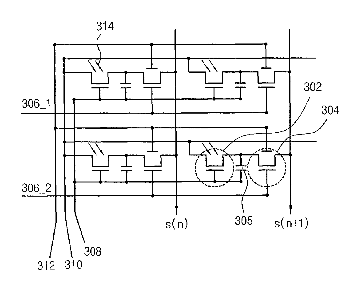
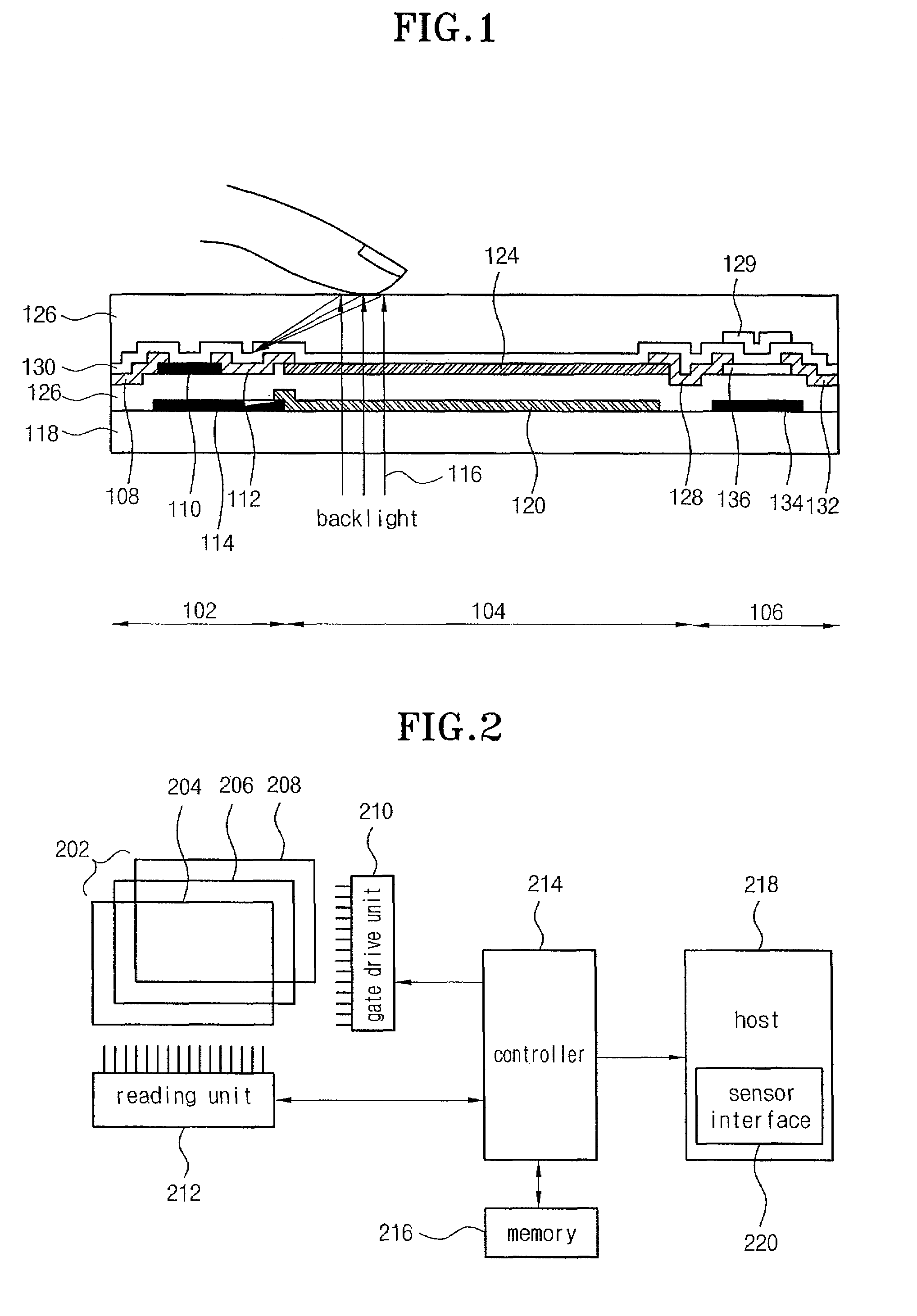
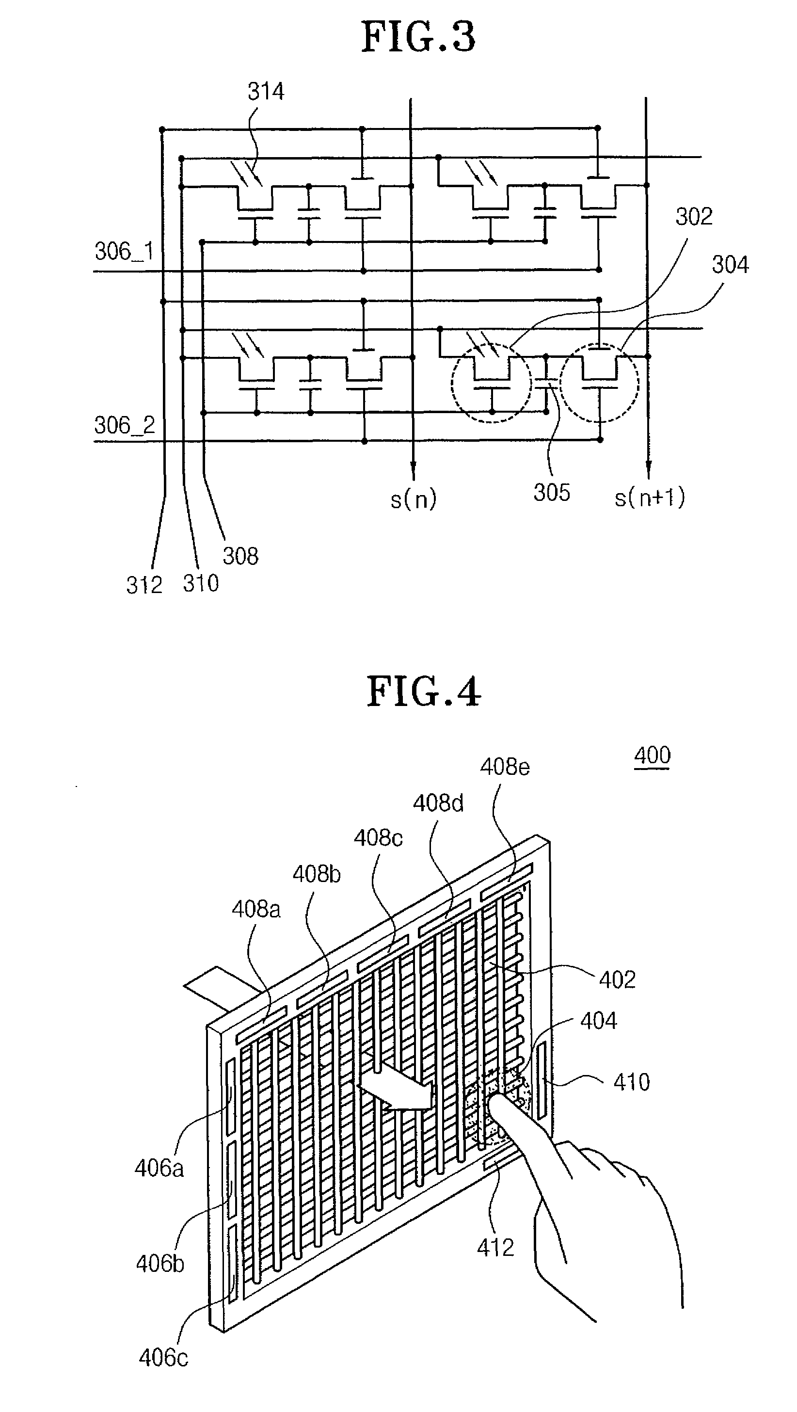
The present invention aims to solve the problem of increased cost and size in integrating fingerprint recognition devices with liquid crystal display devices. The invention provides a liquid crystal display device with an integrated fingerprint recognition device, minimizing the increase in price and size of the final product. This is achieved by integrating a photosensitive sensor device comprising a sensor thin film transistor, a switch thin film transistor, and an electricity charging unit, in each pixel in the inside of an array substrate or color filter substrate of a liquid crystal display device. Overall, the invention allows for both image display and fingerprint recognition to be performed by one liquid display device.

Problems solved by technology

However, since the password input mode is likely to be hacked into, various modes have been developed lately for recognizing biometrical information such as fingerprints.
However, there is a problem in that the price and volume of a resulting product are increased because it is necessary to buy and mount a separate fingerprint device on a liquid crystal display panel or in a separate space.

Method used


Image

  • Liquid crystal display device performing both image display mode and fingerprint recognition mode
  • Liquid crystal display device performing both image display mode and fingerprint recognition mode
  • Liquid crystal display device performing both image display mode and fingerprint recognition mode

Examples


Embodiment Construction

[0024]Hereinafter, a preferred embodiment of the present invention will be described with reference to the accompanying drawings. In the following description and drawings, the same reference numerals are used to designate the same or similar components, and so repetition of the description for the same or similar components will be omitted.

[0025]FIG. 4 shows a construction of a liquid crystal display device in accordance with an embodiment of the present invention. The term “liquid display device” used herein is intended to include a device for only displaying images as usual and a device for performing both image display and fingerprint recognition. As shown in FIG. 4, a display panel of a liquid crystal display device 400 is divided into an image display region 402 and a finger print recognition region 404. However, these two regions are formed in one panel. The image display region 402 is the same as a conventional TFT-LCD and will be briefly described with reference to FIG. 6. ...


PUM

PropertyMeasurementUnit
photosensitiveaaaaaaaaaa

Abstract

Disclosed is a liquid crystal display device of novel construction, in which a fingerprint recognition device is integrally formed with the liquid crystal display device, thereby minimizing the increase in the price and size of a final product. The liquid crystal display device comprises an image display panel and a fingerprint recognition panel which are integrally formed, wherein the image display panel comprises a scan drive unit which sequentially turns on rows formed in the image display panel for each frame in order to display images, and a data drive unit which outputs data signals to a turned-on row provided in the image display panel, and wherein the fingerprint recognition panel comprises a switch control unit which sequentially turns on rows formed in the fingerprint recognition panel for each frame in order to perform fingerprint recognition, and a reading unit, to which fingerprint information recognized from a turned-on row is outputted.

Description

[0001]This application is continuation of U.S. patent application Ser. No. 10 / 331,530, which was filed Dec. 30, 2002 now U.S. Pat. No. 7,418,117.BACKGROUND OF THE INVENTION[0002]1. Field of the Invention[0003]The present invention relates to a liquid crystal display device, and more particularly to a liquid crystal display device capable of performing both image display mode and fingerprint recognition mode. The liquid crystal display device according to the present invention is more effective than a piezoelectric sensor or an optical sensor, which uses one or more semiconductor components and is generally employed in fingerprint recognition-based security / authentication techniques, in view of reliability and costs. Furthermore, the present invention is directly applicable to STN or TFT-LCD products which themselves have a very wide applicability, so that it can be employed in an electronic commerce system, a security system, a personal recognition / authentication system or the like....

Claims


Application Information

Patent Timeline
Patent Type & Authority Patents(United States)
IPC IPC(8): G06K9/00G02F1/133G06T1/00G09G3/36G02F1/1333G06F1/16G02F1/1368G06F3/041G02F1/13
CPCG06F3/0412G09G2300/0809G06K9/0004G02F1/13338G09G3/3648G06F1/1601G06F2203/0339G02F2001/13312G06F3/042G02F1/13312G06V40/1318G02F1/13
Inventor KIM, CHOONG HOOPARK, KYU CHANGSHIM, MIN SOO
Owner HYDIS TECH CO LTD
Learn More