
Frequency profiles for non-contact range measurement with multi-scale analysis

a frequency profile and non-contact technology, applied in the direction of liquid/fluent solid measurement, instruments, using reradiation, etc., can solve the problems of significant signal loss, loss, and difficulty in measuring fluid velocity and distance in partially filled open channels, etc., to achieve the effect of minimizing computation effort and improving accuracy and resolution

Active Publication Date: 2019-03-21
HACH CO
View PDF1 Cites 19 Cited by
  • Summary
  • Abstract
  • Description
  • Claims
  • Application Information

AI Technical Summary

Benefits of technology

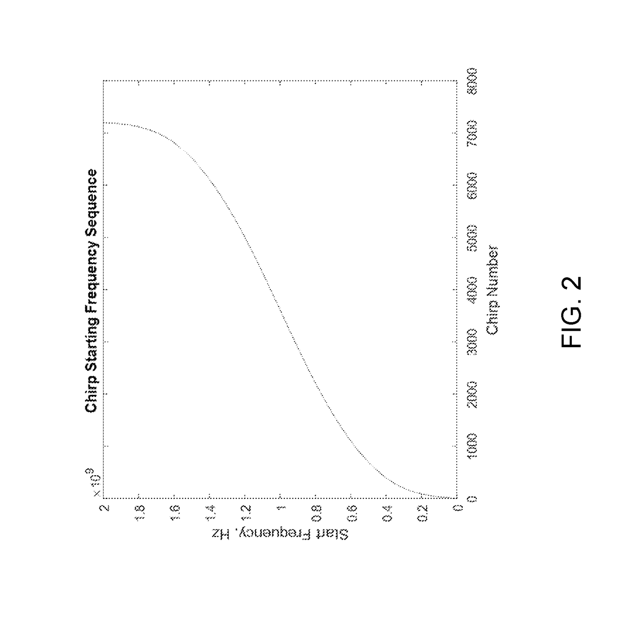
The patent describes a method for constructing a frequency profile of an emitted signal for use in a non-contact ranging system with multi-scale spectral analysis. The method involves determining a set of frequency chirps with linear frequency modulation and a predetermined bandwidth and slope, and organizing them into groups. The groups are then parsed and ordered end to end in time. The method also includes re-enumerating and reordering the frequency chirps to create a non-linear step profile that extends over a predetermined total bandwidth. The non-linear step profile is designed to control the magnitude of unwanted spectral side lobes. The patent also describes a system for measuring fluid velocity and range within a flow channel using the constructed frequency profile.

Problems solved by technology

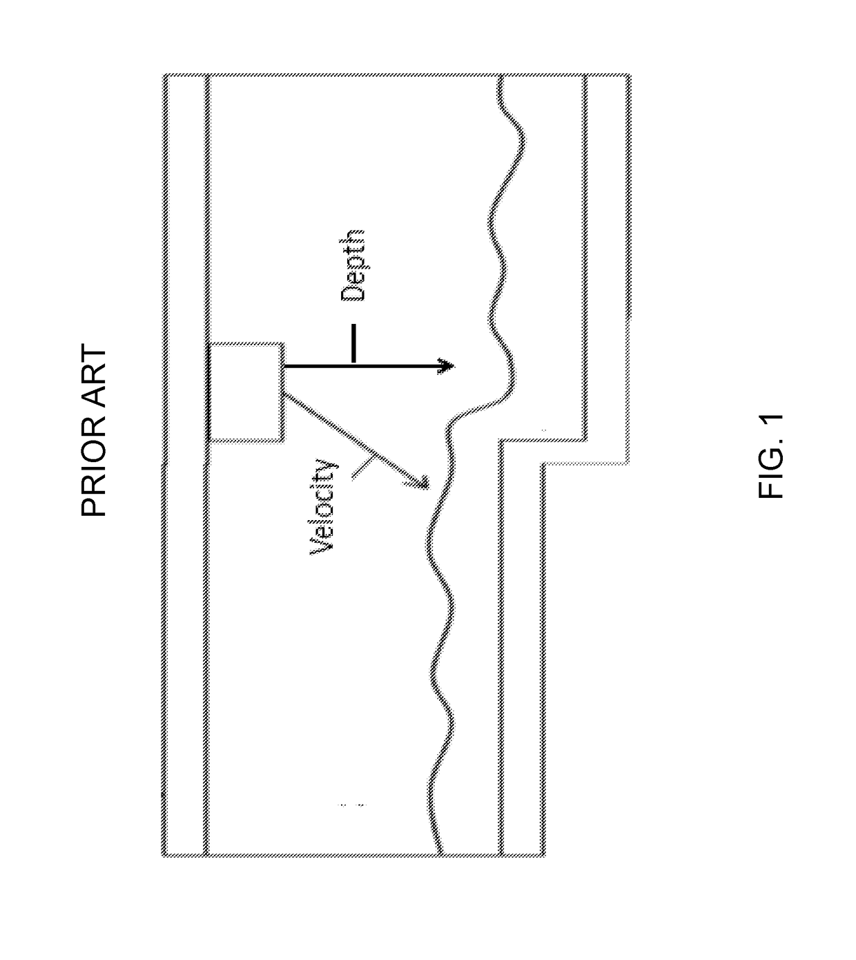
Measuring fluid velocity and distance in partially filled open channels (for example, sewers, irrigation ditches, etc.) using radar is especially challenging.
When measuring velocity of a flowing fluid, the signal must typically be emitted slantwise to the fluid surface, resulting in significant signal loss.
The loss occurs because most of the incident energy glances off the fluid surface and continues propagating away from the sensor.
Measuring distance in open channels may be very challenging when high accuracy is required (for example, millimeter accuracy at a maximum range of only a few meters).
However, if velocity and level are not measured at the same point, computations of volumetric flow rate may be in error.
To measure distance and velocity at the same point, both the velocity and distance signals must typically be emitted in a slant-wise fashion to the fluid, which results in most of the radar energy glancing off the fluid surface.
The resultant high loss adds significantly to the difficulty of making a valid distance measurement.
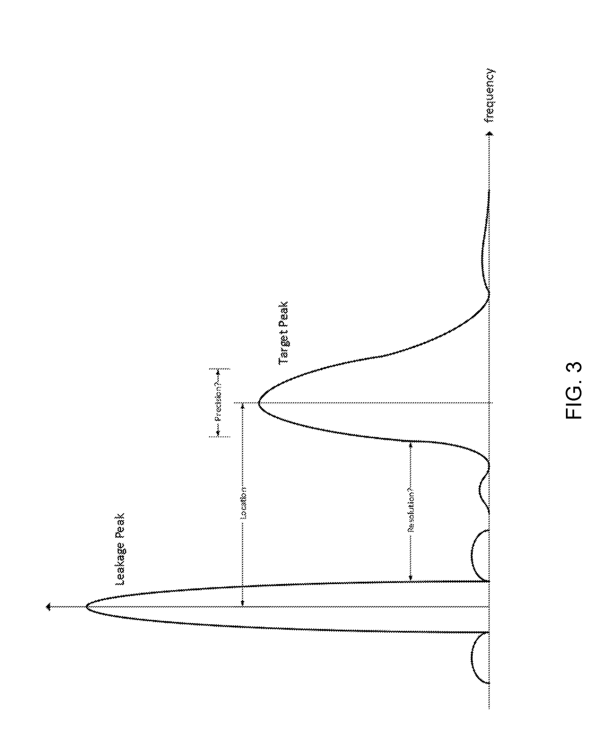
Measurement becomes particularly difficult as the range gets shorter (in part as a result of leakage peaks and associated side lobes in the spectrum of the received signal).
If stepped LFM sequences are not designed correctly, the device may not function as intended.
An FMCW ranging device designed for this range requires a very large FFT window that may be impractical, waste valuable computing time, and have large associated power consumption.
However, conventional FMCW schemes cannot be implemented with multi-scale analysis, as a result of interference from high amplitude side lobes, aliasing, etc. during spectral analysis.

Method used


Image

  • Frequency profiles for non-contact range measurement with multi-scale analysis
  • Frequency profiles for non-contact range measurement with multi-scale analysis
  • Frequency profiles for non-contact range measurement with multi-scale analysis

Examples


Embodiment Construction

[0038]It will be readily understood that the components of the embodiments, as generally described and illustrated in the figures herein, may be arranged and designed in a wide variety of different configurations in addition to the described representative embodiments. Thus, the following more detailed description of the representative embodiments, as illustrated in the figures, is not intended to limit the scope of the embodiments, as claimed, but is merely illustrative of representative embodiments.

[0039]Reference throughout this specification to “one embodiment” or “an embodiment” (or the like) means that a particular feature, structure, or characteristic described in connection with the embodiment is included in at least one embodiment. Thus, the appearance of the phrases “in one embodiment” or “in an embodiment” or the like in various places throughout this specification are not necessarily all referring to the same embodiment.

[0040]Furthermore, described features, structures, ...


PUM


Abstract

A method for constructing a frequency profile of an emitted signal suitable for use in a non-contact ranging system with multi-scale spectral analysis includes determining N stepped frequency chirps, wherein each frequency chirp of the N stepped frequency chirps has a linear FM modulation of predetermined bandwidth and slope, and wherein a starting frequency for each of the plurality of stepped frequency chirps is chosen so that a non-linear step profile is created which extends over a predetermined total bandwidth, sorting the plurality of N stepped frequency chirps into P sub-sequences, where P is equal to the product of decimation factors to be used in the multi-scale spectral analysis, and ordering the P sub-sequences end to end in time.

Description

BACKGROUND[0001]The following information is provided to assist the reader in understanding technologies disclosed below and the environment in which such technologies may typically be used. The terms used herein are not intended to be limited to any particular narrow interpretation unless clearly stated otherwise in this document.[0002]Non-contact sensors can be used to measure an object's distance and / or velocity. Non-contact sensors often emit energy signals such as one or more acoustic or electromagnetic signals toward an object. By analyzing the reflected signals, distance and velocity of the object may be determined. Examples of non-contact sensors include, for example, sonar, radar, laser, and UV devices.[0003]Measuring fluid velocity and distance in partially filled open channels (for example, sewers, irrigation ditches, etc.) using radar is especially challenging. When measuring velocity of a flowing fluid, the signal must typically be emitted slantwise to the fluid surface...

Claims


Application Information

Patent Timeline
Patent Type & Authority Applications(United States)
IPC IPC(8): G01S13/58H04B1/69G01S13/10G01S7/4911G01S7/4913G01S17/32
CPCG01S13/582H04B1/69G01S13/10H04B2001/6912G01S17/32G01S17/58G01S17/88G01S7/354G01S7/4913G01S7/536G01F23/284G01F23/2962G01S13/34G01S13/583G01S13/88G01S15/32G01S15/586G01S15/88G01S7/4911G01S7/356
Inventor RICK, DAVID L.
Owner HACH CO
Learn More