Arterial compression device and methods of using the same

Active Publication Date: 2019-03-28
CORMED LTD
View PDF3 Cites 9 Cited by
  • Summary
  • Abstract
  • Description
  • Claims
  • Application Information

AI Technical Summary

Benefits of technology

[0014]In certain embodiments, the wrist plate may be transparent or translucent. Additionally or alternatively, the compression portion may be transparent or translucent. Additionally or alterna

Problems solved by technology

This is in contrast with prior art arterial compression devices whereby the devices obstruct access to the ulnar artery an

Method used


Image

  • Arterial compression device and methods of using the same
  • Arterial compression device and methods of using the same
  • Arterial compression device and methods of using the same

Examples


Embodiment Construction

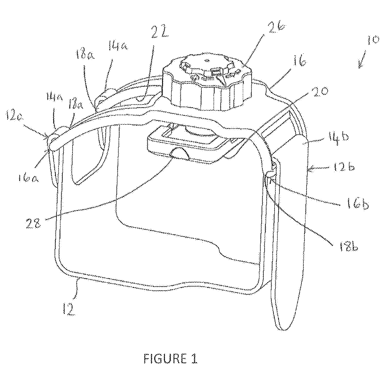
[0056]An arterial compression device 10 according to an embodiment of the present disclosure is shown in FIG. 1. The arterial compression device 10 includes a band 12 for securably fastening the device 10 around a wrist of a subject, and a compression portion in the form of a pad 20. The pad 20 is located on the device 10 in a position such that it is moveable so as to selectively apply pressure to the radial artery of the subject when the device 10 is secured around the wrist of the subject. The pad may be made of or include silicone or a similarly soft and / or resilient material. In certain embodiments, the pad 20 may include a rigid back plate and a soft contact portion for contacting the subject.

[0057]In the non-limiting embodiment shown in FIG. 1, the device 10 includes a wrist plate 16 to which the pad 20 is connected. The wrist plate 16 has a first end 16a that is connected to a first end 12a of the band 12. In the non-limiting embodiment shown in the Figures, the wrist plate ...


PUM


Abstract

An arterial compression device comprising a band for securably fastening the arterial compression device around a wrist of a subject, a compression portion that is moveable so as to selectively apply pressure to the radial artery of the subject, and an aperture permitting access to the ulnar artery of the subject when the arterial compression device is securably fastened around the wrist of the subject.

Description

[0001]The present disclosure relates to an arterial compression device, and in particular to an arterial compression device for applying pressure to the radial artery of a subject. The present disclosure also relates to methods of using an arterial compression device.BACKGROUND[0002]Increasingly, the radial artery is used for access to the arterial vasculature when performing interventional procedures such as angiography or percutaneous coronary intervention (PCI) procedures. This is in contrast to alternative access sites, such as the femoral artery. Radial artery access may be considered to be preferable over femoral artery access for certain procedures as it may allow vascular closure in a vessel that is more easily closed. This may result in less hospital-based recovery time for the patient thereby reducing costs and improving patient comfort.[0003]Following a transradial catheterization procedure, closure of the radial artery puncture site can occasionally result in permanent o...

Claims


Application Information

Patent Timeline
IPC IPC(8): A61B17/135A61B5/1455A61B5/02A61B5/00A61B17/132
CPCA61B17/135A61B5/14552A61B5/02007A61B5/6826A61B17/1325A61B5/14551A61B5/681A61B5/6824A61B5/02A61B17/1322A61B17/132
Inventor BROWN, ADRIAN D.SWIFT, JONATHAN C.BROWN, CHRISTOPHER
Owner CORMED LTD
Why Eureka
Try Eureka