Laser welding method, laser welding structure, and throttle valve device

a laser welding and throttle valve technology, applied in the direction of machines/engines, manufacturing tools, other domestic articles, etc., can solve the problems of reducing the mechanical strength of the final product, unable to accept the reduction of the mechanical strength of the throttle valve device of the internal combustion engine that undergoes, and posing inexpedience, etc., to achieve the effect of reducing the heat capacity, increasing the temperature of the convex portion, and not easily directing the heat to the surrounding portions

Inactive Publication Date: 2005-05-26
DENSO CORP
View PDF8 Cites 7 Cited by
  • Summary
  • Abstract
  • Description
  • Claims
  • Application Information

AI Technical Summary

Benefits of technology

[0014] Further, the above-described laser irradiation is preferably performed by a bulk irradiation that is executed so that the portions to be welded and the stepping portion are at once irradiated using a light source that is aligned in a row. In the bulk irradiation, the whole of the welded portions and the stepping portion are thereby irradiated with the laser beams by slightly broadening an irradiation region to thereby include the stepping portion. This eliminates necessity of changing the period and the procedure for the laser irradiation, so that the process of the laser welding can be prevented from becoming complex.
[0015] Further, the above-described stepping portion is preferably a convex portion. In the convex portion, the laser beams are diffused so that the temperature of the convex portion is increased. Further, the convex portion has a heat capacity lower than the surrounding portions to thereby not easily conduct the heat to the surrounding portions. The melting or burning of the convex portion by the laser irradiation can be securely generated.
[0016] Further, the above-described stepping portion is preferably a concave portion. In the concave portion, the laser beams are diffused so that the temperature of the concave portion is increased. The melting or burning of the concave portion by the laser irradiation can be thereby securely generated.
[0017] Further, the above-described stepping portion is preferably a penetrating portion formed in a spacing from the surface irradiated by the laser beam to a surface where the welded portion is formed. Here, the trace is at least formed in proximity of the irradiated surface of the penetrating portion. The laser beams are diffused in the proximity of the irradiated surface of the penetrating portion, increasing the temperature in the proximity of the irradiated surface of the penetrating portion. The melting or burning in the proximity of the irradiated surface by the laser irradiation can be thereby securely generated.
[0018] Further, the above-described first component is preferably formed by resin molding using a plurality of molding shapes, wherein the stepping portion is a convex portion formed at the resin molding in accordance with fitting surfaces of the plurality of molding shapes. Otherwise, the above-described first component is preferably formed by resin molding using a molding shape, wherein the stepping portion is a convex and concave portion formed in accordance with a pushing pin provided in the molding shape for extracting the first component from the molding shape at the resin molding. This enables visual confirmation of the welding state without adding a process of forming the stepping portion.
[0019] Further, in the above-described throttle valve device of the present invention, the first component constituting the laser welding structure is a throttle valve provided within a throttle body becoming a passage of a fuel for feeding an internal combustion engine. By contrast, the second component is a throttle shaft supporting the throttle valve so that an inclination angle to the passage is able to be changed. This enables visual confirmation of the welding state after the welding operation is finished, even when the welding of the throttle valve and the throttle shaft is executed by the laser irradiation.

Problems solved by technology

This poses inexpediency.
In the above method disclosed in Patent Document 2, necessity of having an opening in the welded portion within the component that is disposed at a position from which the laser beam is radiated, eventually poses a problem that decreases a mechanical strength of the final product.
In particular, decreasing the mechanical strength is not accepted by a throttle valve device of an internal combustion engine that undergoes thermal stresses derived from significant mechanical vibrations or rapid thermal fluctuations.
Further, since the welded portion is observed through the opening, observing the welded portion is sometimes difficult depending on lighting conditions.
This involves difficulty in confirming, thereby possibly resulting in missing confirming.

Method used


Image

  • Laser welding method, laser welding structure, and throttle valve device
  • Laser welding method, laser welding structure, and throttle valve device
  • Laser welding method, laser welding structure, and throttle valve device

Examples


Embodiment Construction

[0033] Hereinbelow, a throttle valve device of an embodiment according to the present invention will be explained in detail with reference to drawings.

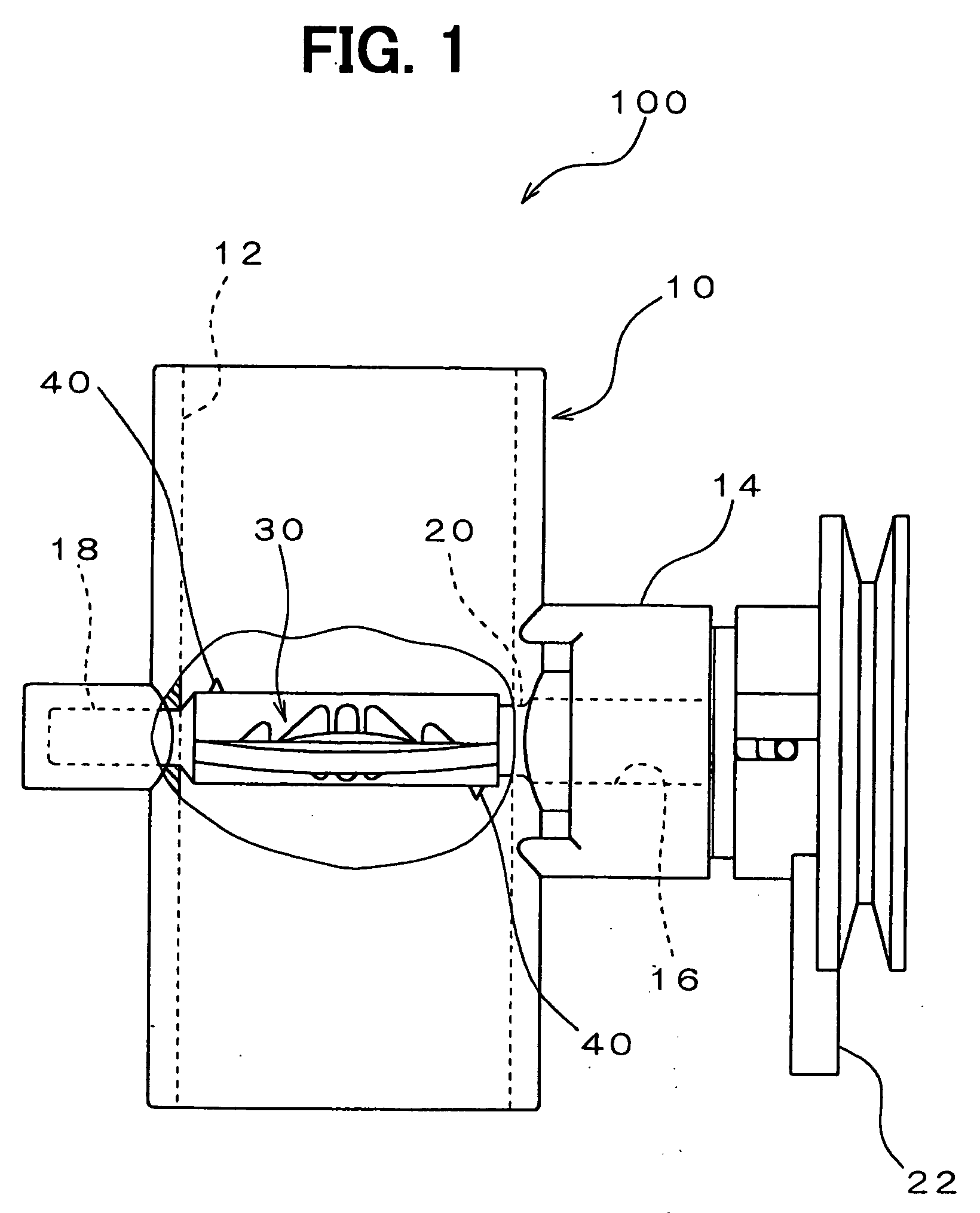
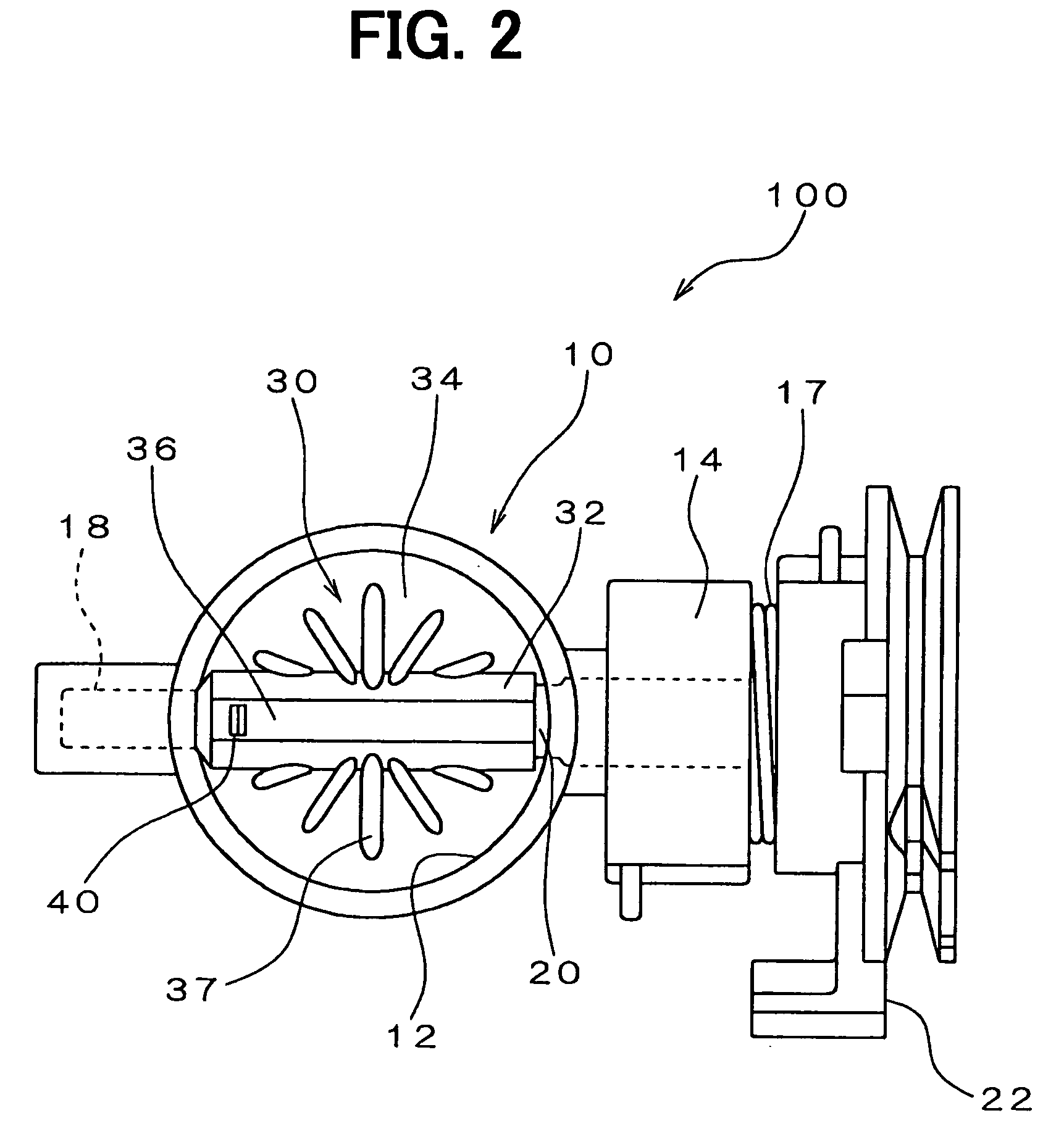
[0034]FIG. 1 is a front view of a throttle valve device of an embodiment. FIG. 2 is a plan view of the throttle valve device shown in FIG. 1. As shown in FIGS. 1, 2, the throttle valve device 100 of the embodiment includes a throttle body 10, a throttle shaft 20, and a throttle valve 30.

[0035] The throttle body 10 forms an intake passage 12 that feeds an internal combustion engine (not shown) with fuel, being molded as a single-piece using resin material such as PBT (saturated polyester resin) and nylon. In a middle of the throttle body 10, a shaft insertion portion 14 is formed to outwardly protrude. Within the shaft insertion portion 14, a shaft aperture 16 is formed to be perpendicular to a central axis of the intake passage 12. Further, within the shaft insertion portion 14, a circular ring groove is formed. Within the circular ...


PUM

PropertyMeasurementUnit
thicknessaaaaaaaaaa
moving speedaaaaaaaaaa
widthaaaaaaaaaa

Abstract

A throttle valve and a throttle shaft are welded to each other. Here, the throttle valve is made of resin material having a transmission property for a laser beam and includes a convex portion on a surface thereof irradiated by the laser beam. By contrast, the throttle shaft is made of resin material having a absorption property for a laser beam. The throttle valve and the throttle shaft are disposed so that their mutual portions to be welded face each other. Laser beams are radiated from the surface of the throttle valve to the mutual portions to be welded so that the convex portion is included in a part of an irradiated region.

Description

CROSS REFERENCE TO RELATED APPLICATIONS [0001] This application is based on and incorporates herein by reference Japanese Patent Application No. 2003-390955 filed on Nov. 20, 2003. FIELD OF THE INVENTION [0002] The present invention relates to a laser welding method where resin materials are welded to each other by laser irradiation, further relating to a laser welding structure using the method, and a throttle valve device using the method. BACKGROUND OF THE INVENTION [0003] It is known that a mechanical connection between two components made of resin material is performed by welding using laser irradiation. For instance, a resin-made throttle valve and a resin-made throttle shaft included in a throttle valve device of an internal combustion engine are connected with each other by using a laser welding device (refer to Patent Document 1). In this throttle valve device, the throttle valve being a first component as a welded object is formed of resin material that has a tendency to t...

Claims


Application Information

Patent Timeline
Patent Type & Authority Applications(United States)
IPC IPC(8): F02D9/10B23K26/32B29C65/16B29L31/30F16K1/22
CPCB29C65/1635B29C65/8253B29C66/1122B29C66/863B29C66/939B29C66/919B29C66/9161B29C66/934B29C65/1654B29C65/1687B29C66/54F16K1/221B29C66/5221B29C65/00B29C66/65B29C66/652B29C66/71B29C66/73921B29K2067/006
Inventor SANO, RYOHIRATA, MITSUTAKAKAWAMOTO, YASUNORINISHINA, HIROYUKIMATSUI, YOUICHI
Owner DENSO CORP
Why Eureka
Try Eureka