Adjustable spine distraction implant

a technology of spine distraction and implant, which is applied in the field of adjustable spine distraction implant, can solve the problems of pressure on the spinal cord and nerve, bone spurs and problems with joints, and swelling of the soft tissues of joints, and achieve the effect of reducing discomfor

Active Publication Date: 2019-03-28
LIFE SPINE INC
View PDF5 Cites 0 Cited by
  • Summary
  • Abstract
  • Description
  • Claims
  • Application Information

AI Technical Summary

Benefits of technology

[0014]One embodiment provides a minimally invasive adjustable implant and method for alleviating discomfort associated with the spinal column.
[0015]One embodiment provides a method and apparatus for relieving pain by relieving the pressure and restrictions on the blood vessels and nerves associated with the spine. This can be accomplished using an adjustable implant and method which distracts the spinous process of adjacent vertebra in order to alleviate the problems caused by spinal stenosis, facet arthropathy, and similar conditions.
[0018]One embodiment provides an adjustable implant adapted for increasing the volume and / or cross sectional area of the spinal canal and / or the neural foramen as the implant is positioned between adjacent spinous processes.
[0019]One embodiment provides a method for relieving pain due to conditions such as spinal stenosis and facet arthropathy. The method includes the steps of accessing adjacent first and second spinal processes of the spinal column and using an adjustable implant to distract these processes a sufficient amount in order to increase the volume and / or cross sectional area of the spinal canal and relieve pain.
[0030]Various embodiments of the method and apparatus can be used to increase the volume and / or cross sectional area of the spinal canal thereby alleviating restrictions on vessels and nerves associated therewith, and reducing pain caused by such restrictions.

Problems solved by technology

This narrowing puts pressure on the spinal cord and nerves and can cause pain.
It may involve many joints in the body where it wears away the tough tissue (cartilage) that keeps the joints in place and can cause bone spurs and problems with joints.
It causes the soft tissues of the joints to swell and can affect internal organs and systems.
However, it is not a common cause of spinal stenosis but can cause severe damage, especially to joints.
In many cases there may be no symptoms of spinal stenosis, or symptoms may appear slowly and get worse over time.
Symptoms may include: loss of control of the bowel or bladder; problems having sex; and pain, weakness, or loss of feeling in one or both legs.

Method used


Image

  • Adjustable spine distraction implant
  • Adjustable spine distraction implant
  • Adjustable spine distraction implant

Examples


Embodiment Construction

[0093]FIGS. 16 through 18 are perspective views of a portion of a spinal column 30. Spinal column 30 includes a plurality of vertebrae 40 with spinous processes (e.g., 100 and 110). Spinal column 30 also includes the spinal cord and nerve roots (not shown for clarity). In one embodiment the apparatus can be implanted to increase the volume and / or cross sectional area of spinal canal thereby alleviating restrictions on vessels and nerves 60 associated therewith, and reducing pain caused by such restrictions.

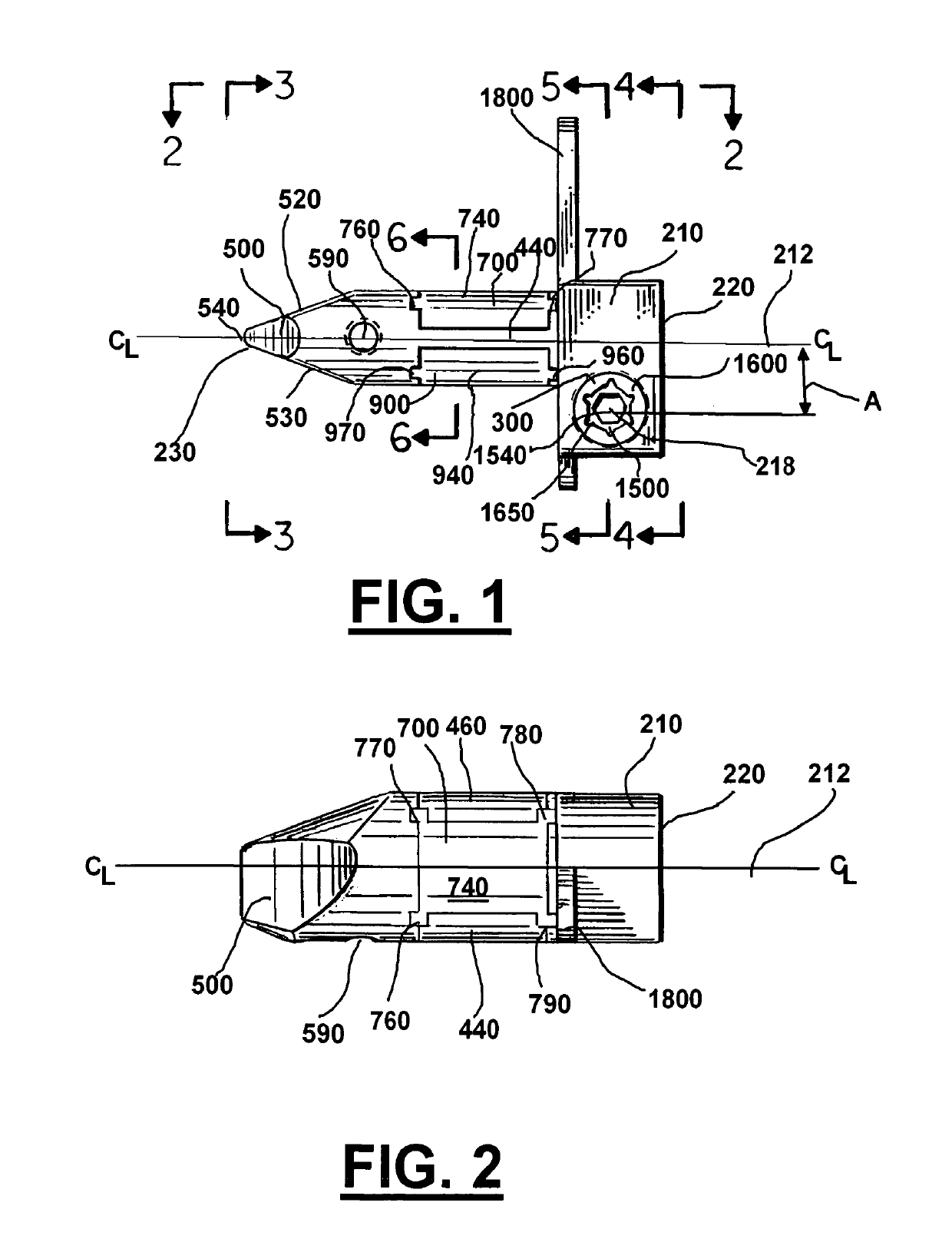
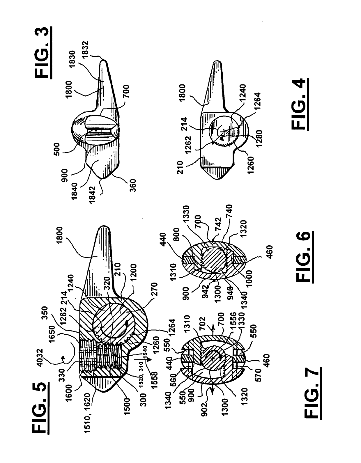
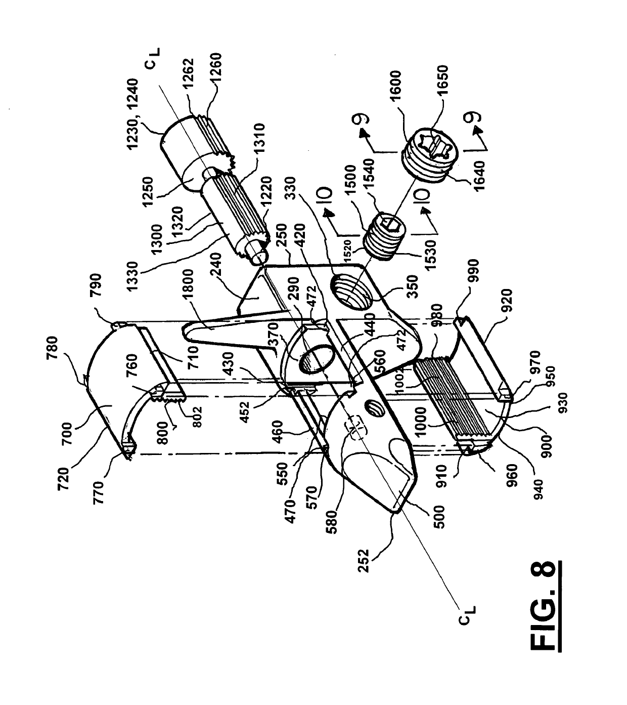
[0094]For purposes of implantation between adjacent first and second spinous processes 100 and 110 of spinal column 30 (see FIGS. 16 through 18), adjustable implant 200 can be configured as shown in FIGS. 1 through 43. First and second spinous processes 100 and 110 are exposed using appropriate surgical techniques and thereafter, adjustable implant 200 is positioned so that upper wedging member 700 engages first spinous process 100, and lower wedging member 900 engages second spin...


PUM


Abstract

An adjustable spine distraction implant alleviates pain associated with spinal stenosis and facet arthropathy by expanding the volume and / or cross sectional area in the spinal canal and / or neural foramen. The adjustable implant provides a spinal extension inhibitor. The implant includes elliptical or oval shaped adjustable member or spacer for positioning between and adjustably spacing apart the spinous processes.

Description

CROSS-REFERENCE TO RELATED PATENT APPLICATIONS[0001]This application is a continuation of U.S. application Ser. No. 15 / 090,257, filed Apr. 4, 2016, which is a continuation of U.S. application Ser. No. 13 / 247,664, filed Sep. 28, 2011, which are incorporated herein by reference in their entireties.BACKGROUND[0002]The spine includes a row of 26 bones in the back and allows a person to stand up straight and bend over. The spine also protects a person's spinal cord from being injured. In people with spinal stenosis, the spine is narrowed in one or more of three parts: (1) the space at the center of the spine; (2) the canals where nerves branch out from the spine; and (3) the space between vertebrae (the bones of the spine). This narrowing puts pressure on the spinal cord and nerves and can cause pain.[0003]Caused by aging spinal stenosis is most common in men and women over 50 years old. Younger people who were born with a narrow spinal canal or who hurt their spines may also get spinal ...

Claims


Application Information

Patent Timeline
Patent Type & Authority Applications(United States)
IPC IPC(8): A61B17/70A61B17/00A61F2/44
CPCA61B17/7064A61B17/7065A61F2/4405A61B17/7055A61B2017/00858A61B17/7068A61B17/7047
Inventor WOLTERS, MADELINE C.BUTLER, MICHAEL S.
Owner LIFE SPINE INC
Why Eureka
Try Eureka