Plastic valve for preventing distortion

Active Publication Date: 2019-03-28
LEE SANG SEON
View PDF12 Cites 0 Cited by
  • Summary
  • Abstract
  • Description
  • Claims
  • Application Information

AI Technical Summary

Benefits of technology

The invention is a plastic valve that prevents distortion. It includes a connection member made of plastic and a flange member made of plastic that is formed at one end of the connection member. The valve is designed so that a pipe can be connected by inserting it into a hole in the connection member. The flange member also includes a distortion prevention member that reduces the force that causes distortion. This reduces the chance of the valve becoming damaged or leaking during use.

Problems solved by technology

This distortion twists the pipe.

Method used


Image

  • Plastic valve for preventing distortion
  • Plastic valve for preventing distortion
  • Plastic valve for preventing distortion

Examples


first embodiment

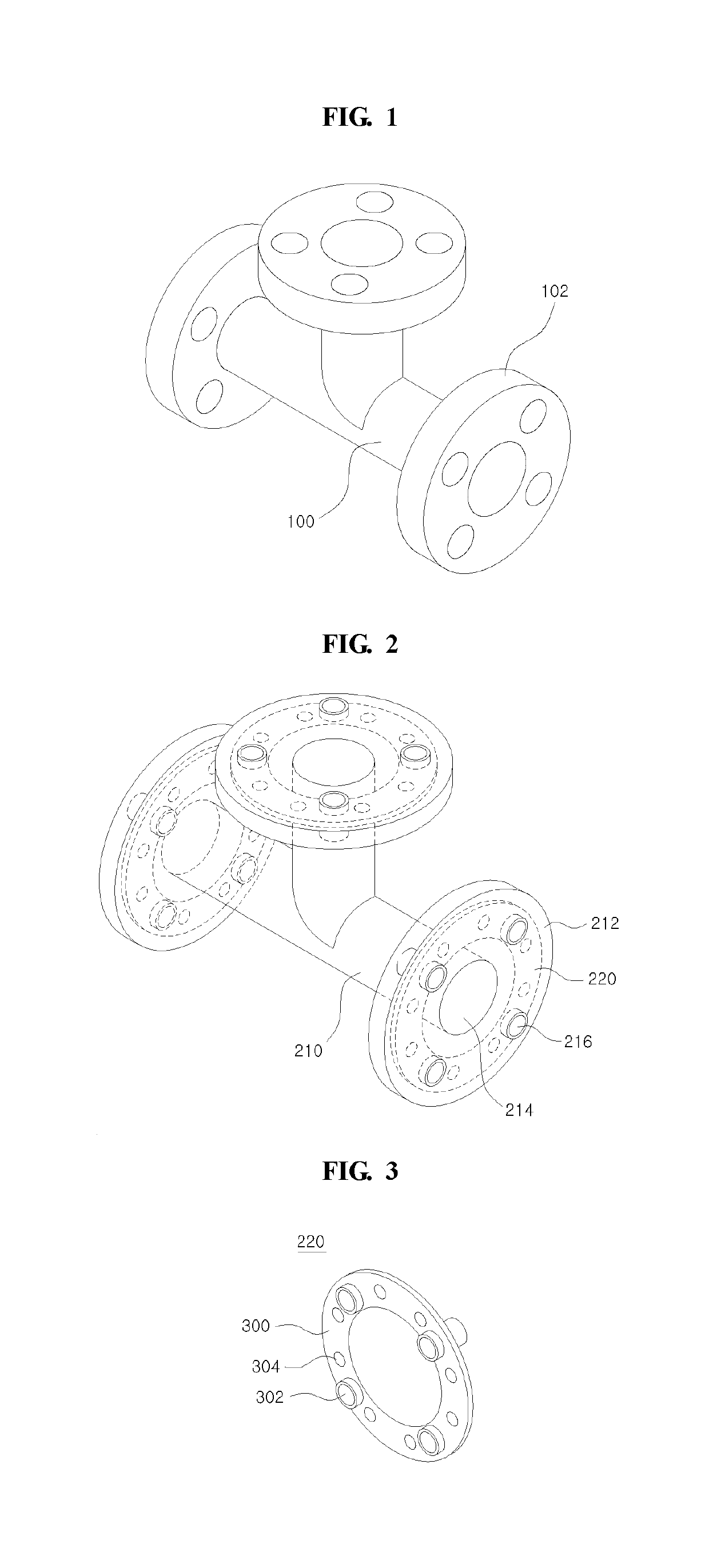
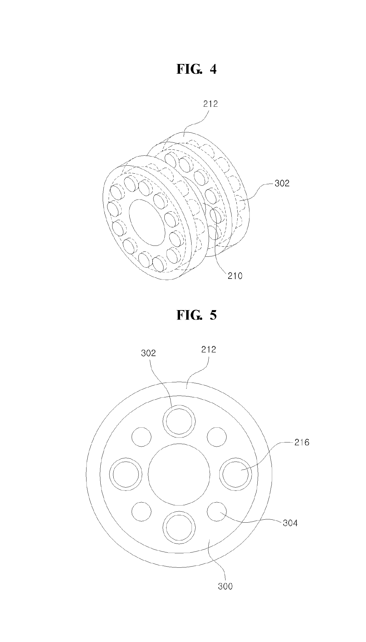
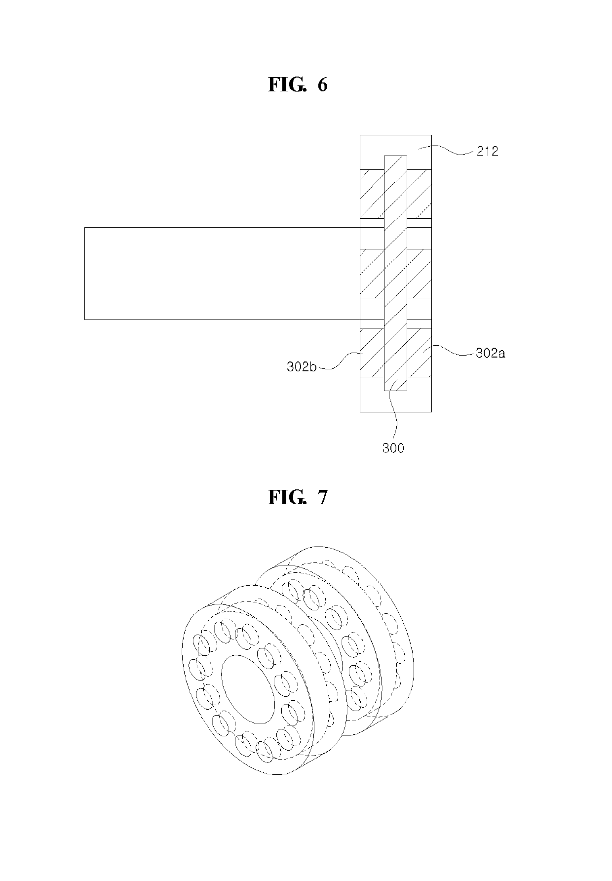
[0046]FIG. 2 is a perspective view illustrating a plastic valve according to the invention, FIG. 3 is a view illustrating a metal member according to one embodiment of the invention, and FIG. 4 is a view for describing effect of the plastic valve of the invention. FIG. 5 and FIG. 6 are sectional views illustrating the plastic valve in FIG. 2, FIG. 7 is a perspective view illustrating a plastic valve compared with the plastic valve of the invention, and FIG. 8 is a view illustration a connection structure of a pipe.

[0047]In FIG. 2, a plastic valve 200 of the present embodiment is made up of plastic material, and includes a connection member 210 and at least one flange member 212.

[0048]The connection member 210 connects pipes, a hole 214 into which the pipe is inserted being formed at a central part of the connection member 210.

[0049]The flange member 212 is formed at an end part of the connection member 210, and includes at least one hole 216. As shown in FIG. 8, the plastic valve 20...

second embodiment

[0074]FIG. 9 is a sectional view illustrating a plastic valve according to the invention.

[0075]In FIG. 9, in the plastic valve of the present embodiment, case members 900a and 900b may be respectively formed on the connection member 210 and the flange member 212.

[0076]In one embodiment, the connection member 210 and the flange member 212 may be made up of fluoride resin, and the case members 900a and 900b may be made up of engineering plastic. For example, the case members 900a and 900b may be made up of polyphenylenethers resin composition including polyphenylenethers resin and polystyrene resin.

[0077]Of course, the case members 900a and 900b as the engineering plastic may be made up of POLYIMIDE, POLYSULFONE, POLY PHENYLENE SULFIDE, POLYAMIDE IMIDE, POLYACRYLATE, POLYETHER SULFONE, POLYETHER ETHER KETONE, POLYETHER IMIDE, LIQUID CRYSTAL POLYESTER, POLYETHER KETONE, etc. and their combination. If the case members 900a and 900b are formed with the engineering plastic, the plastic va...

third embodiment

[0079]FIG. 10 is a view illustrating a plastic valve according to the invention, and FIG. 11 is a view illustrating connection structure of the plastic valves in FIG. 10.

[0080]In FIG. 10, the plastic valve 1000 includes a connection member 1010 and a flange member 1012.

[0081]A metal member 1014 is formed in the flange member 1012.

[0082]The metal member 1014 may include a body 1020, a first protrusion 1022 and a second protrusion 1024.

[0083]Whole of the first protrusion 1022 is included in the flange member 1012 (dent state), and a part of the second protrusion 1024 is projected outside (protrusion state) of the flange member 1012. Here, the first protrusion 1022 and the second protrusion 1024 faces based on a specific portion of the body 1020, and the first protrusion 1022 is separated from an internal surface of the flange member 1012.

[0084]In one embodiment, the second protrusion 1024 may have higher length than the first protrusion 1022.

[0085]Referring to FIG. 11, a second protru...


PUM

PropertyMeasurementUnit
Forceaaaaaaaaaa
Lengthaaaaaaaaaa

Abstract

A plastic valve for preventing distortion is disclosed. The plastic valve comprises a connection member made up of plastic and a flange member made up of plastic and formed at an end part of the connection member. Here, a metal member is formed in the flange member, and the metal member includes a body and at least one protrusion projected from the body in a direction of an end of the flange member.

Description

CROSS-REFERENCE TO RELATED APPLICATIONS[0001]This application is a continuation application of PCT application PCT / KR2017 / 007663, which was filed on Jul. 17, 2017, and which claims priority from Korean Patent Application No. 10-2016-0092122 filed with the Korean Intellectual Property Office on Jul. 20, 2016, Korean Patent Application No. 10-2016-0092159 filed with the Korean Intellectual Property Office on Jul. 20, 2016, and Korean Patent Application No. 10-2016-0092178 filed with the Korean Intellectual Property Office on Jul. 20, 2016. The disclosures of the above patent applications are incorporated herein by reference in their entirety.BACKGROUND1. Field of the Invention[0002]The invention relates to a plastic valve capable of preventing distortion.2. Description of the Related Art[0003]A plastic value is made up of plastic, and has generally a structure of following FIG. 1.[0004]FIG. 1 is a view illustrating a conventional plastic valve.[0005]In FIG. 1, the plastic valve includ...

Claims


Application Information

Patent Timeline
IPC IPC(8): F16K27/00F16L23/032F16L41/02B29C45/14
CPCF16K27/00F16L23/032F16L41/021B29C45/14467B29L2031/7506B29K2309/08B29K2101/12F16L23/003F16L47/14F16L57/00B29C45/14
Inventor LEE, SANG SEON
Owner LEE SANG SEON
Why Eureka
Try Eureka