Imaging lens, projection-type display apparatus, and imaging apparatus
- Summary
- Abstract
- Description
- Claims
- Application Information
AI Technical Summary
Benefits of technology
Problems solved by technology
Method used
Image

Examples
Embodiment Construction
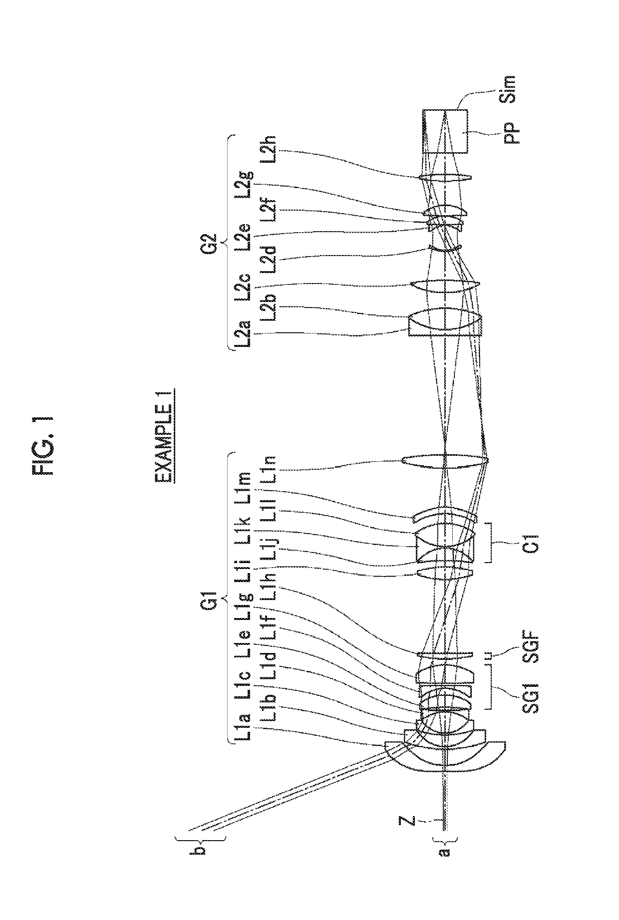
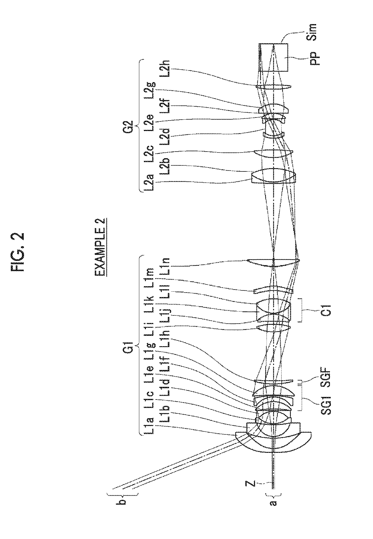
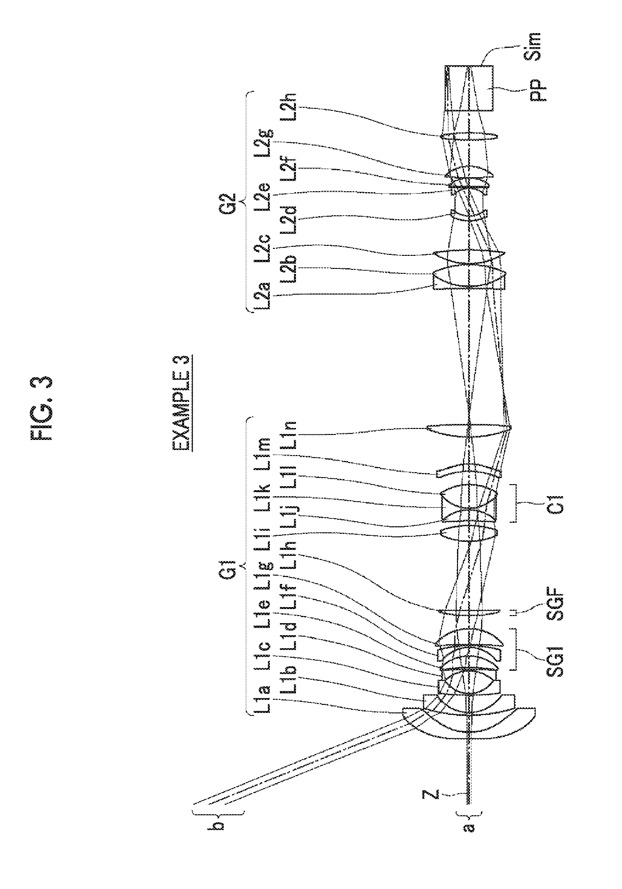
[0041]Hereinafter, an embodiment of the present invention will be described in detail with reference to the accompanying drawings. FIG. 1 is a cross-sectional view illustrating a lens configuration of an imaging lens according to an embodiment of the present invention. The configuration example shown in FIG. 1 is in common with the configuration of an imaging lens of Example 1 described later. In FIG. 1, a left side is a magnified side, and a right side is a reduced side. In addition, FIG. 1 shows a state of being focused on an infinite object, and shows an on-axis light flux a and a light flux b of the maximum angle of view together.
[0042]This imaging lens is mounted on, for example, a projection-type display apparatus, and can be used in projecting image information displayed on a light valve onto a screen. In FIG. 1, on the assumption of a case of being mounted on the projection-type display apparatus, an optical member PP assumed to be a filter, a prism and the like which are us...
PUM
 Abstract
Description
Claims
Application Information