
Rotary mop cleaner

Active Publication Date: 2019-04-04
HONORS CO LTD
View PDF0 Cites 6 Cited by
  • Summary
  • Abstract
  • Description
  • Claims
  • Application Information

AI Technical Summary

Benefits of technology

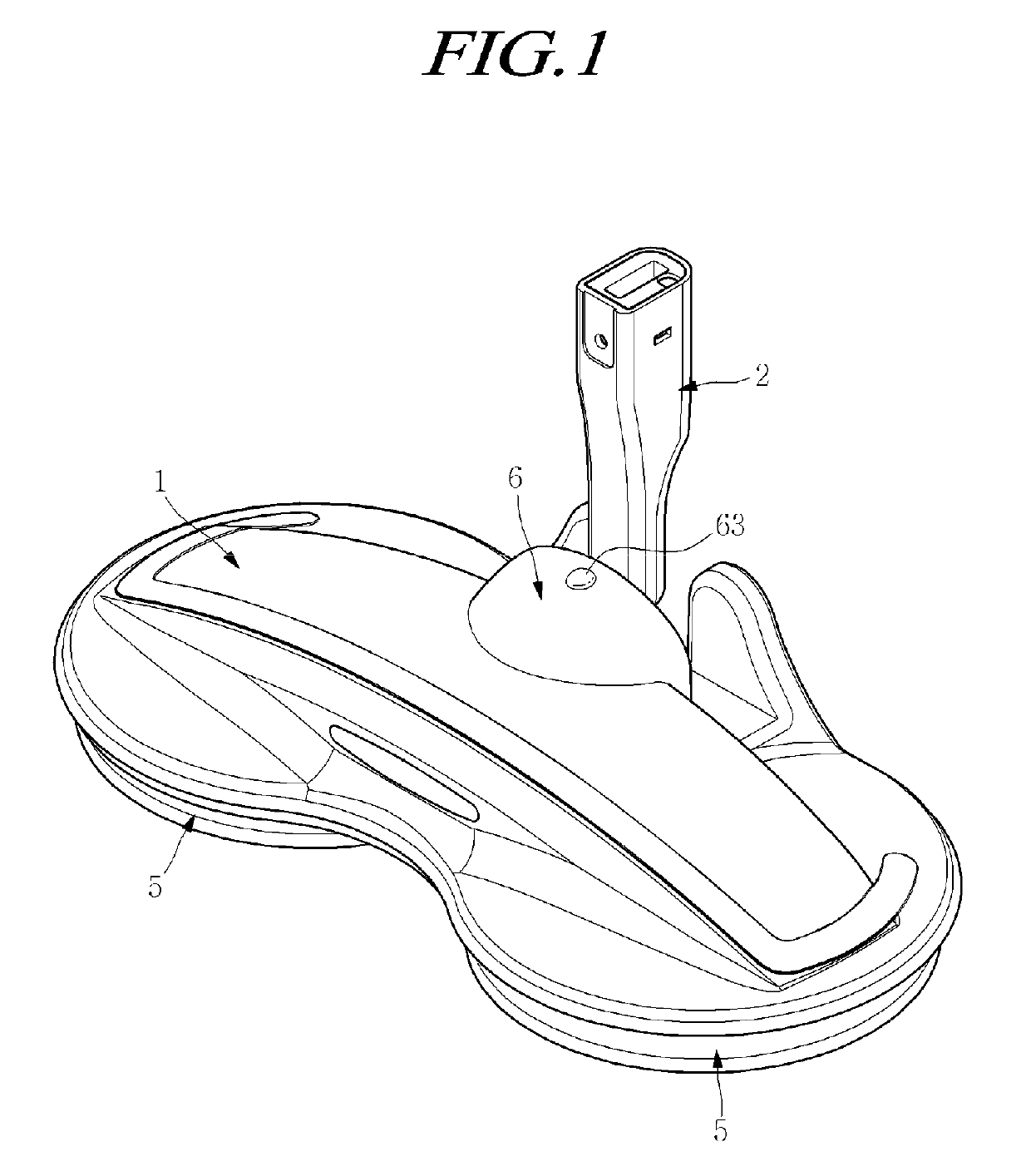
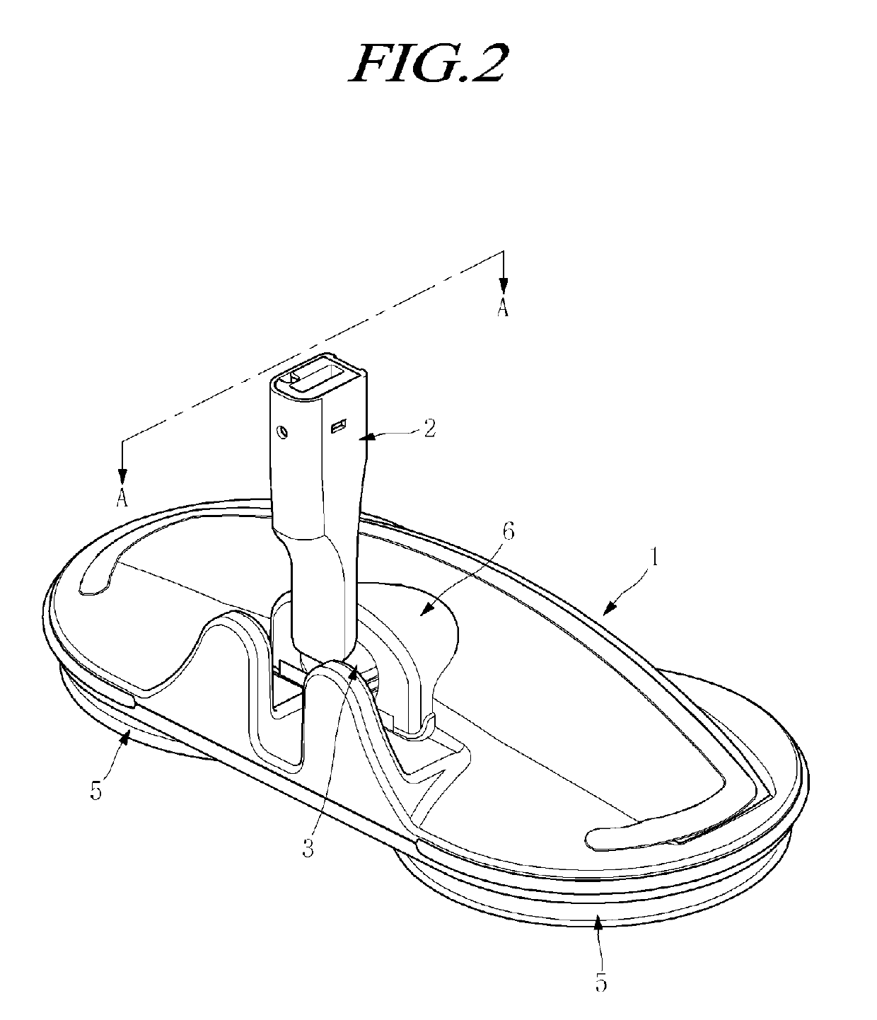
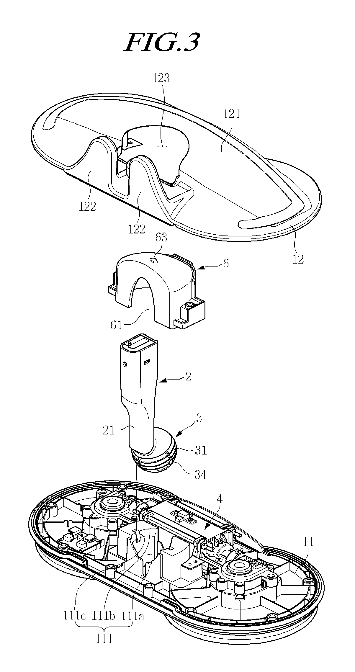
The present invention provides a rotary mop cleaner that can stand by itself and is much more durable. It includes a ball joint that allows for reliable pivoting and tilting movements of the stick with respect to the body. The stick can be erected in an upright state and the risk of dislocation can be prevented. The stick is pivotable and adjustable to various angles, allowing for cleaning in narrow spaces and improving the ability of the body to advance in a straight line. The rotary plate, which is coupled to the rotary shaft drive unit, can be displaced along a floor surface, reducing noise and vibration during cleaning and ensuring stable rotation of the rotary mop.

Problems solved by technology

Generally, when performing indoor cleaning at home, accompanying household labor is unavoidable since, after removing garbage and dust using a broom or a vacuum cleaner, it is necessary to repeat the process of removing the hair or dust remaining on the floor surface with a wet mop or a dry mop.
The hinge-type connecting portion described above has problems in that a metal hinge is inevitably used, in that the durability of the coupling between the rotary bar and the plastic main body is poor, and in that when the cleaner is not used, it is difficult to make a handle portion vertically stand by itself with respect to the main body.

Method used


Image

  • Rotary mop cleaner
  • Rotary mop cleaner
  • Rotary mop cleaner

Examples


Embodiment Construction

[0041]The purposes, specific advantages, and novel features of the present disclosure will become more apparent from the following detailed description and examples taken in conjunction with the accompanying drawings. It should be noted that in adding reference numerals to the constituent elements of respective drawings in this specification, the same constituent elements will be denoted by the same numerals if possible, even if the constituent elements are illustrated on different drawings. In the following description of the present disclosure, a detailed description for the related known technology will be omitted when it is determined that the detailed description may make the subject matter of the present disclosure rather unclear. In this specification, the terms such as “first” and “second” are used to distinguish one constituent element from another constituent element, but the constituent elements are not limited by the terms. In the accompanying drawings, some constituent ...


PUM


Abstract

The present disclosure relates to a rotary mop cleaner. The rotary mop cleaner includes: a ball joint provided at a lower end of a stick and having a pair of engagement projections extending outwards from both side ends thereof; a rotary plate drive unit configured to rotate a rotary plate; a body configured to accommodate a lower hemisphere of the ball joint and having guide grooves configured to allow a pair of engagement projections to be inserted therein in order to ensure the rotation of the ball joint; a ball cover configured to cover an upper hemisphere of the ball joint; and a rotary plate bolted to the rotary shaft of the rotary plate drive unit, which extends to the lower portion of the body, so as to be movable relative thereto with a clearance therebetween.

Description

CROSS-REFERENCE TO RELATED APPLICATIONS[0001]This application claims priority from Korean Patent Application No. 10-2017-0127192, filed on Sep. 29, 2017, which is hereby incorporated by reference for all purposes as if fully set forth herein.BACKGROUND OF THE INVENTION1. Field of the Invention[0002]The present disclosure relates to a rotary mop cleaner, and more particularly, to a rotary mop cleaner in which a stick is freely rotatable in a body and a rotary plate is mounted to have a clearance in an axial direction.2. Description of the Prior Art[0003]Generally, when performing indoor cleaning at home, accompanying household labor is unavoidable since, after removing garbage and dust using a broom or a vacuum cleaner, it is necessary to repeat the process of removing the hair or dust remaining on the floor surface with a wet mop or a dry mop.[0004]In order to at least alleviate such inconvenience, a wet mop cleaner (Patent Document 1) capable of performing wiping by rotationally dr...

Claims


Application Information

Patent Timeline
IPC IPC(8): A47L13/20A47L11/282
CPCA47L13/20A47L11/282A47L11/283A47L11/40A47L11/4038A47L11/4075A47L11/16A47L11/4036A47L11/4069
Inventor CHUNG, UN HWA
Owner HONORS CO LTD
Learn More