Robot

a robot and robot technology, applied in the field of robots, can solve the problems of large number of components, complex configuration of the robot, and high labor and time requirements for assembly, maintenance, and the like of the robo

Inactive Publication Date: 2019-04-04
SEIKO EPSON CORP
View PDF4 Cites 8 Cited by
  • Summary
  • Abstract
  • Description
  • Claims
  • Application Information

AI Technical Summary

Benefits of technology

[0005]An advantage of some aspects of the invention is to solve at least a part of the problems...

Problems solved by technology

However, in the robot in the past, because the pulleys and the hub are separate bodies, the number of components is large and the configuration of the robot...

Method used


Image

  • Robot
  • Robot
  • Robot

Examples


embodiment

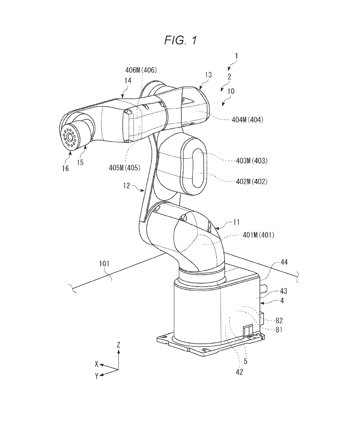
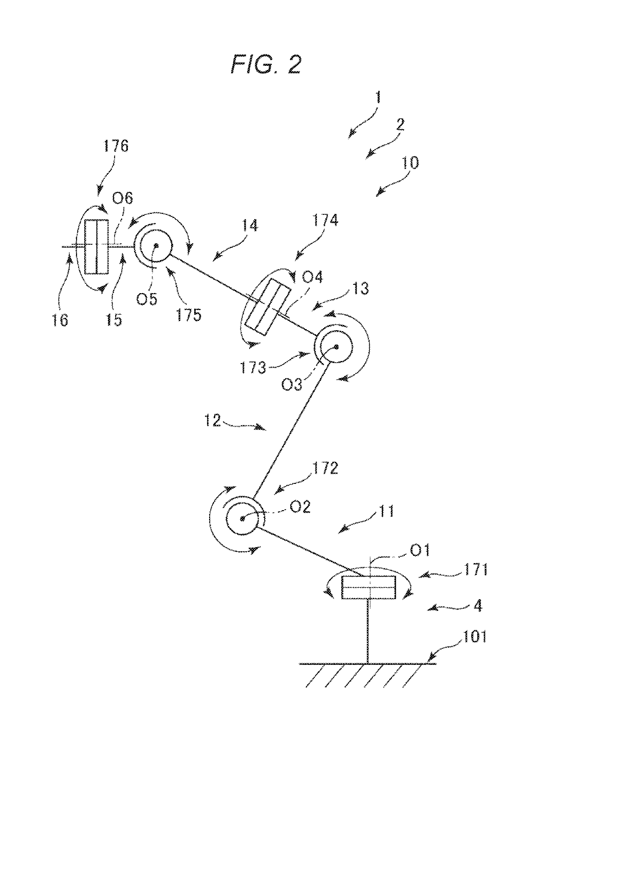
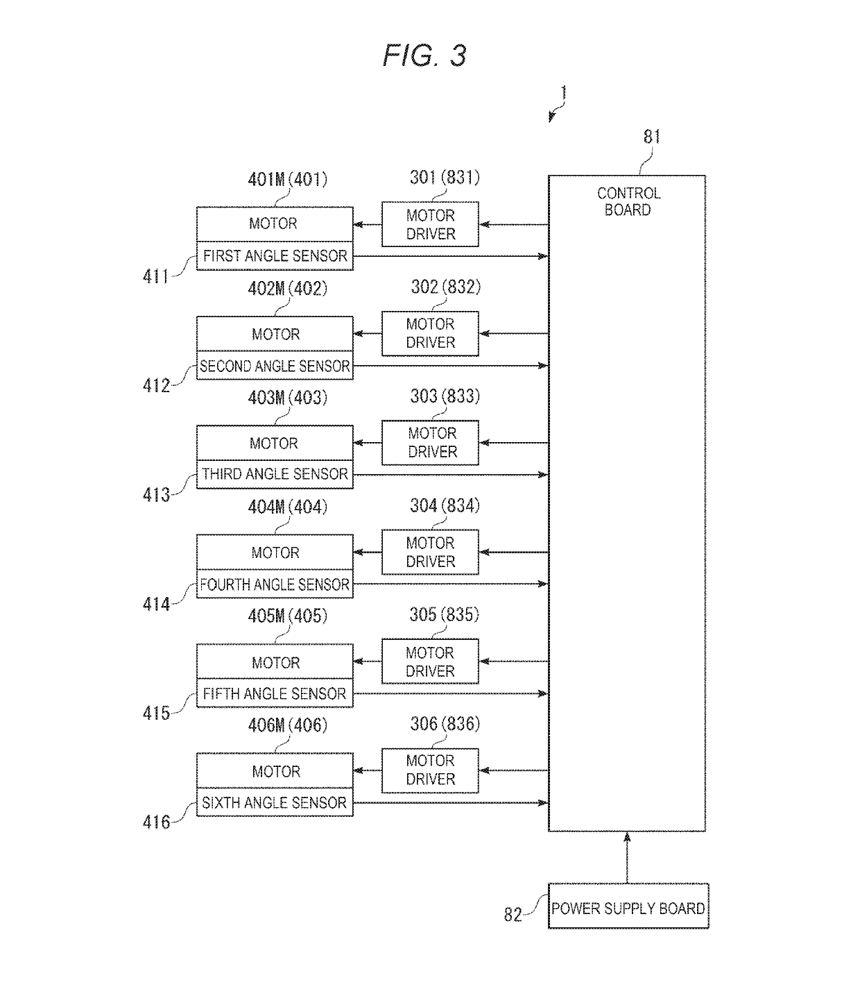
[0040]FIG. 1 is a perspective view showing a robot according to an embodiment of the invention. FIG. 2 is a schematic diagram of the robot shown in FIG. 1. FIG. 3 is a block diagram showing a main part of the robot shown in FIG. 1. FIG. 4 is a perspective view showing a base and a first arm of the robot shown in FIG. 1. FIG. 5 is a perspective view showing the base of the robot shown in FIG. 1. FIG. 6 is a perspective view showing the base of the robot shown in FIG. 1. FIG. 7 is a perspective view showing the base of the robot shown in FIG. 1. FIG. 8 is a perspective view showing the base and the first arm of the robot shown in FIG. 1. FIG. 9 is a sectional view showing the base of the robot shown in FIG. 1. FIG. 10 is a cutaway view obtained by cutting away a part of the base of the robot shown in FIG. 1. FIG. 11 is a cutaway view obtained by cutting away a part of the base of the robot shown in FIG. 1. FIG. 12 is a cutaway view obtained by cutting away a part of the base and the f...


PUM


Abstract

A robot includes an arm, a driving source including a turning output shaft and configured to generate a driving force for turning the arm, an output member configured to turn together with the output shaft, and a braking mechanism including a friction plate configured to turn together with the output shaft and moving in an axial direction of the output shaft, the braking mechanism braking the turning of the output shaft.

Description

BACKGROUND1. Technical Field[0001]The present invention relates to a robot.2. Related Art[0002]There is known a robot including a base and a robot arm including a plurality of arms (links). One arm of adjacent two arms of the robot arm is turnably coupled to the other arm via a joint section. An arm on the most proximal end side (the most upstream side) is turnably coupled to the base via a joint section. The joint sections are driven by motors. The arms turn according to the driving of the joint sections. For example, a hand is detachably attached to an arm on the most distal end side (the most downstream side) as an end effector. For example, the robot grasps an object with the hand, moves the object to a predetermined place, and performs predetermined work such as assembly.[0003]JP-A-2011-177845 (Patent Literature 1) discloses a SCARA robot. In such a SCARA robot or a robot such as a vertical articulated robot, a mechanism including a motor, two pulleys, and a belt laid over the ...

Claims


Application Information

Patent Timeline
IPC IPC(8): B25J9/04B25J9/12B25J9/00B25J19/00
CPCB25J9/046B25J9/126B25J9/0009B25J19/0004
Inventor NIU, AKIO
Owner SEIKO EPSON CORP
Why Eureka
Try Eureka