Lifter

Active Publication Date: 2019-04-04
HAIYAN AIHUA MACHINERY CO LTD
View PDF1 Cites 3 Cited by
  • Summary
  • Abstract
  • Description
  • Claims
  • Application Information

AI Technical Summary

Benefits of technology

[0013]The advantages of the present invention are as follows. The present invention has an appropriate structure, with the use of a foldable and retractable support base and a bracket mechanism which can be turned over. The present invention can be folded and stored when not in use, so that it is easy to store and organize and occupies less storage space. With the use of lifting tube group, the position adjustment of the bracket assembly of the lifter is realized through a hand-drive transmission, so that the present invention can satisfy different work requirements of the height and achieve the lifting of the

Problems solved by technology

Currently, the objects are manually lifted, which not only requires high intensity labor, but also is dangerous.
Moreover, the object can fall down easily, thereby causing serious damages to the object, or even worse, the object may be destroyed.
Further, the working efficiency of such method is low.
The height of the existing lifter is adjustable, whereas the size of the carrier bracket is not adjustable, so the application scope is limited and less unive

Method used


Image

  • Lifter
  • Lifter
  • Lifter

Examples


embodiment 1

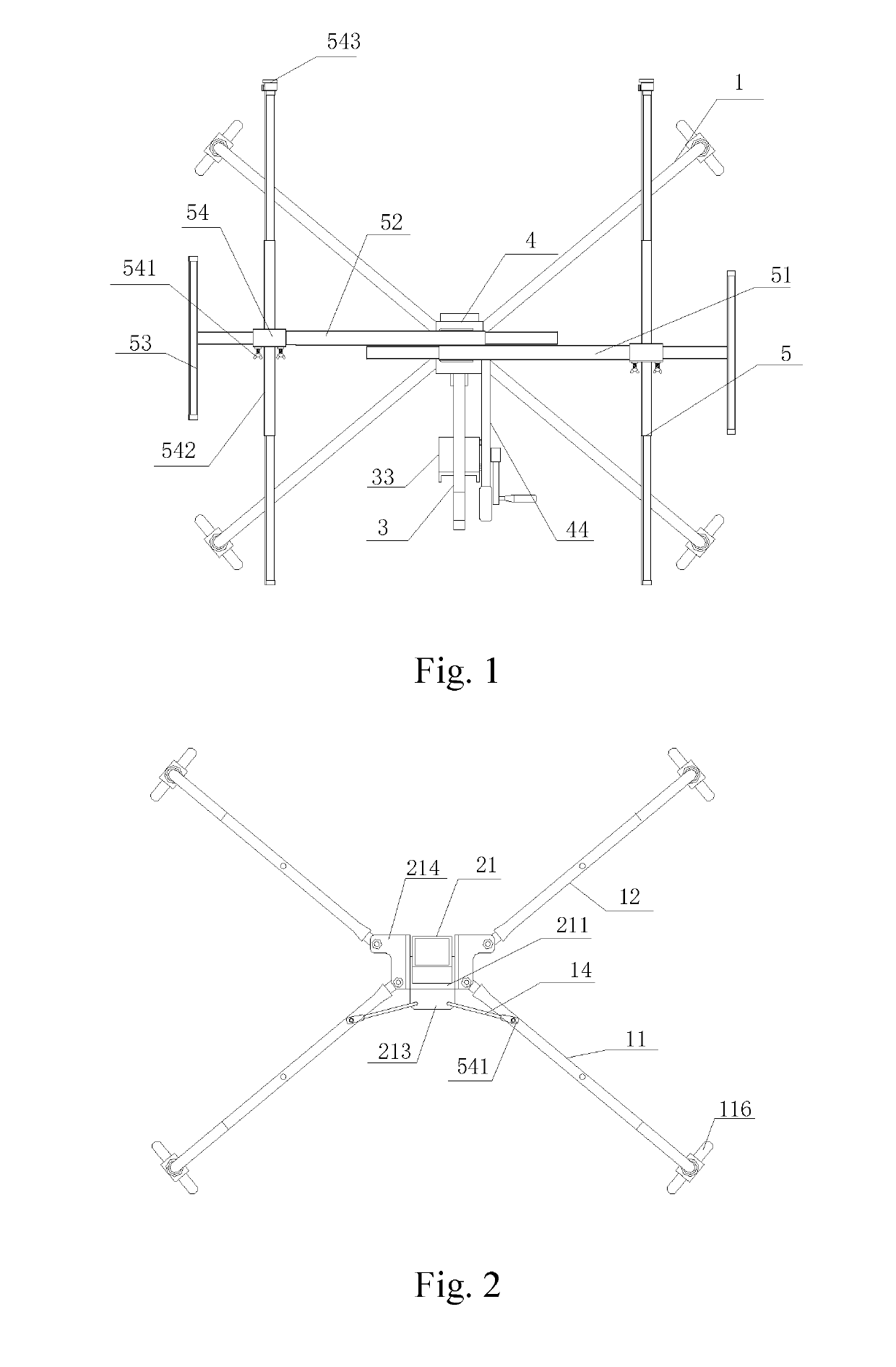
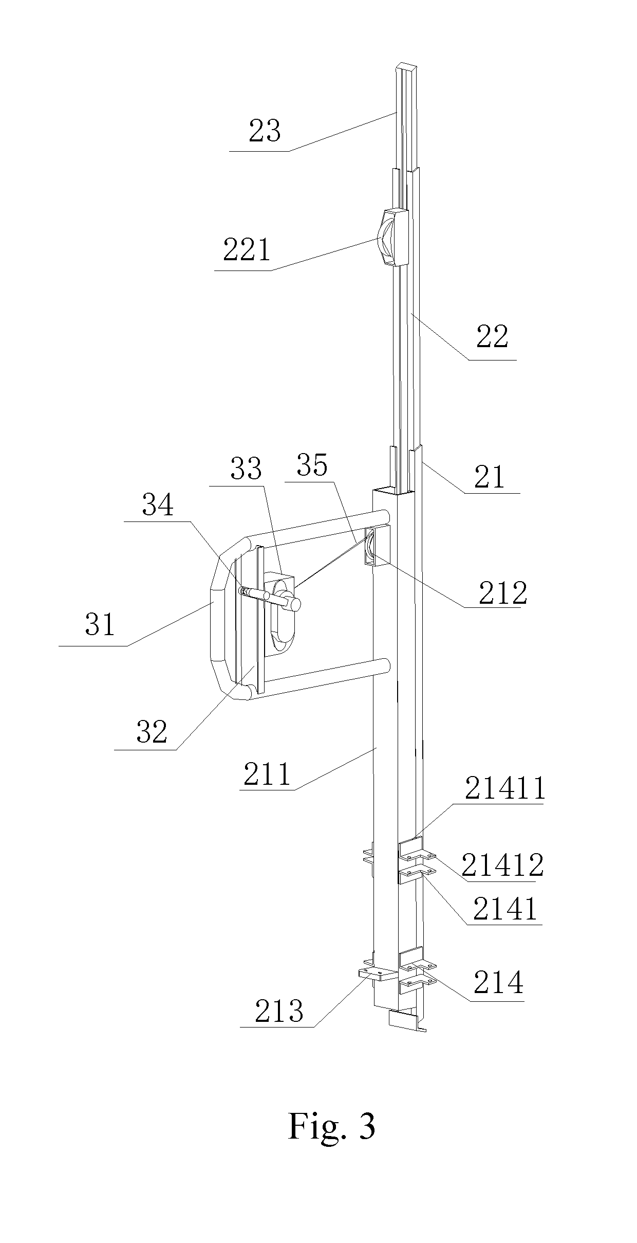
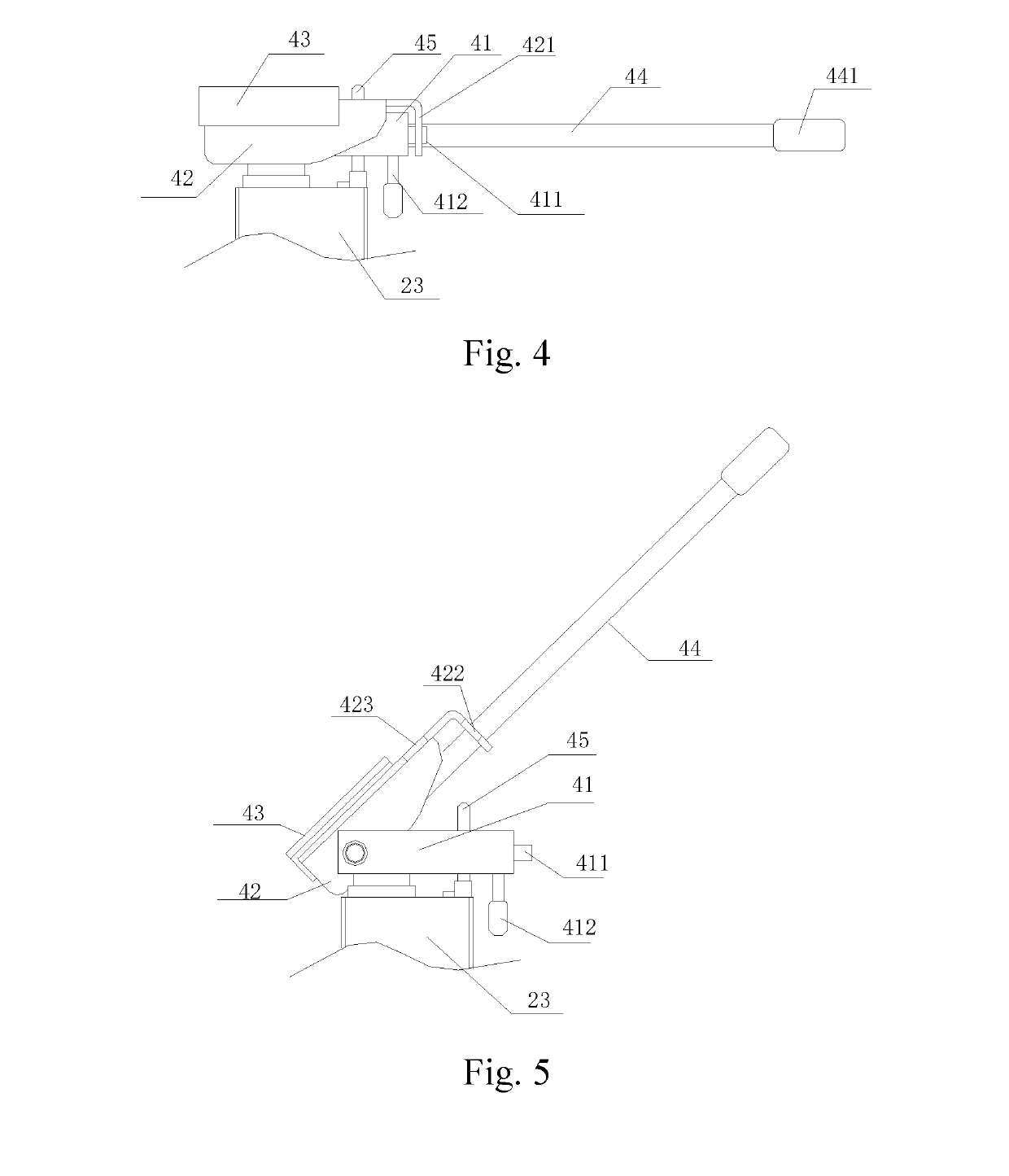
[0025]Referring to FIG. 1-FIG. 8, the lifter of the present invention includes a support base 1, a first elevating stand assembly 2, a first elevating-drive mechanism 3, a turning-drive mechanism 4 and a bracket mechanism 5. A lower pan of the first elevating stand assembly 2 is provided with two sets of first fixing, racks 214. The support base 1 is symmetrically mounted on the first fixing racks 214. One side of the first elevating stand assembly 2 is provided with a first elevating-drive mechanism 3. A first elevating stand 22 is mounted inside the first elevating stand assembly 2. The first elevating-drive mechanism 3 drives the first elevating stand 22 to move through a transmission mechanism 33. The first elevating stand 22 is provided with a second elevating stand 23. The turning-drive mechanism 4 is provided with a support base 41. The support base 41 is mounted on the top of the second elevating stand 23. One end of the support base 41 is hinged to a movable support frame 4...

embodiment 2

[0026]Referring to FIGS. 4, 5, 8, 9, and 10, the lifter of the present invention includes: a support base 1, a second elevating stand assembly 6, a hand-driven elevating mechanism 7, a turning-drive mechanism 4 and a bracket mechanism 5. A lower portion of the second elevating stand assembly 6 is provided with the support base 1. The hand-driven elevating mechanism 7 is arranged on one side of the second elevating stand assembly 6. The hand-driven elevating mechanism 7 is internally provided with a drive gear. A third elevating stand 62 is mounted inside the second elevating stand assembly 6. A side wall of the third elevating stand 62 is provided with a rack 622. The rack 672 cooperates with the drive gear. The hand-driven elevating mechanism 7 drives the third elevating stand 62 to move through driving the gear. The third elevating stand 62 is provided with a fourth elevating stand 63. A side wall of the third elevating stand 62 is provided with a drive roller 621. The drive rolle...


PUM


Abstract

A lifter includes a support base, a first elevating stand assembly, a first elevating-drive mechanism, a turning-drive mechanism and a bracket mechanism. A lower portion of the first elevating stand assembly is provided with two sets of first fixing racks. The support base is symmetrically mounted on the first fixing racks. One side of the first elevating stand assembly is provided with a first elevating-drive mechanism. A first elevating stand is installed inside the first elevating stand assembly. The first elevating-drive mechanism drives the first elevating stand to move through the transmission mechanism. The turning-drive mechanism is provided with a support base. One end of the support base is hinged to a movable support frame. The other end of the support base is provided with a locking assembly. The turning-drive mechanism is provided with a bracket mechanism.

Description

CROSS REFERENCE TO RELATED APPLICATIONS[0001]This application is based upon and claims priority to Chinese Patent Application No. 201710903500X, filed on Sep. 29, 2017, and Chinese Patent Application No. CN2017109033254, filed on Sep. 29, 2017, the entire contents of which are incorporated herein by reference.TECHNICAL FIELD[0002]The present invention relates to the field of object transportation, and more particularly to a lifter.BACKGROUND[0003]In areas such as home furnishing, etc., the objects usually need to be lifted to complete the work. Currently, the objects are manually lifted, which not only requires high intensity labor, but also is dangerous. Moreover, the object can fall down easily, thereby causing serious damages to the object, or even worse, the object may be destroyed. Further, the working efficiency of such method is low. The height of the existing lifter is adjustable, whereas the size of the carrier bracket is not adjustable, so the application scope is limited ...

Claims


Application Information

Patent Timeline
IPC IPC(8): B66F5/02B66F3/02
CPCB66F5/02B66F3/02B66F2700/03B66F3/00B66F7/02B66F7/22
Inventor JIN, AIYUJIN, YANBIN
Owner HAIYAN AIHUA MACHINERY CO LTD
Why Eureka
Try Eureka