Method and apparatus for controlling a double-acting pneumatic actuator

Active Publication Date: 2019-04-04
FISHER CONTROLS INT LLC
View PDF2 Cites 0 Cited by
  • Summary
  • Abstract
  • Description
  • Claims
  • Application Information

AI Technical Summary

Benefits of technology

This patent describes a method and system for controlling the position of a double-acting pneumatic actuator while also adjusting its stiffness. This can be achieved by measuring the position of the actuator and using control signals to adjust the pressures in the two pneumatic chambers, which can increase or decrease the stiffness of the actuator. By doing so, the method enables precise and accurate positioning of the actuator while still controlling its stiffness.

Problems solved by technology

When the forces from the flow of process fluid move the actuator, the process may be adversely affected, and additional wear on actuator components may reduce the life of the actuator.
Stiffness of the actuator presents an engineering trade-off between being able to rapidly control the actuator position and limiting the effect of the buffeting forces in the valve on fluctuations in the position of the actuator.

Method used


Image

  • Method and apparatus for controlling a double-acting pneumatic actuator
  • Method and apparatus for controlling a double-acting pneumatic actuator
  • Method and apparatus for controlling a double-acting pneumatic actuator

Examples


Embodiment Construction

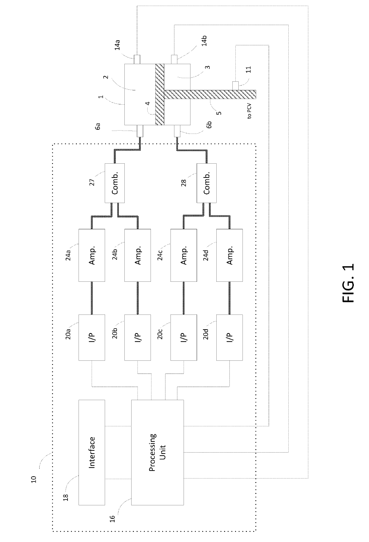
[0015]FIG. 1 illustrates an implementation of a system comprising a double-acting actuator 1 and a positioner 10 for controlling the actuator 1. The positioner 10 can comprise the advanced functionality of a digital valve controller (DVC), but FIG. 1 does not illustrate this functionality. The actuator 1 has an upper pneumatic chamber 2 and a lower pneumatic chamber 3, separated by a piston 4 which is attached to a stem 5 connected to a process control valve (PCV). The process control valve may control fluid flow within a process control system, such as a chemical or other process control plant. Chamber 2 has an outlet 6a which can supply air or another control fluid, or conversely exhaust the control fluid from chamber 2 Likewise, chamber 3 has an outlet 6b which can supply or exhaust the control fluid of chamber 3. As the amount of control fluid changes in one or both of the actuator chambers 2 and / or 3, the piston 4 and the attached stem 5 move to a new position.

[0016]An implemen...


PUM


Abstract

A control loop for a double-acting pneumatic actuator is configured to generate two control signals, one for each of the two pneumatic chambers for the purpose of controlling the actuator position in view of operating constraints on the chamber pressures or the stiffness of the actuator. A numerical indicator of the stiffness may be computed in a variety of ways, for example, as the average of the two chamber pressures. In one embodiment a numerical indicator of stiffness is treated as an output of the system along with the position of the actuator. A multi-input multi-output control loop with position and pressure feedback may be used to simultaneously control the position and the stiffness of the actuator.

Description

FIELD OF THE TECHNOLOGY[0001]The present invention generally relates to control valves and, more particularly, to methods and apparatus for controlling a double-acting pneumatic actuator for a process control valve.BACKGROUND INFORMATION[0002]Many industrial processes use control valves to control the flow rates of fluids through pipes. These control valves are opened and closed by actuators, the positions of which are set by positioners using feedback from actuator position sensors and process settings. The goal of the positioner and actuator combination is to quickly and accurately control actuator position and to minimize deviations in the actuator position in response to the forces generated by the process fluids flowing through the valve.[0003]A double-acting pneumatic actuator changes position by adjusting pressures in two pneumatic chambers, where the pressures push on a piston connected to a stem. The stem, in turn, translates the motion of the piston to adjust an opening of...

Claims


Application Information

Patent Timeline
IPC IPC(8): F15B15/28
CPCF15B15/2815F15B15/149F15B15/202F15B2211/7055F16K31/1223F15B11/042F15B11/044F15B2211/6303F15B2211/6313F15B2211/7053F15B2211/7656
Inventor METSCHKE, CHRISTOPHER S.FONTAINE, MICHAEL R.JUNK, KENNETH W.SMID, DAVID L.
Owner FISHER CONTROLS INT LLC
Why Eureka
Try Eureka