Phase deviation acquisition method and system, and phase calibration method and system

a phase calibration and phase deviation technology, applied in the field of phase calibration methods, can solve the problems of prolonged servicing time and time-consuming methods, and achieve the effect of increasing the speed of phase calibration of the system and fast calibration

Active Publication Date: 2019-04-04
SIEMENS HEALTHCARE GMBH
View PDF0 Cites 2 Cited by
  • Summary
  • Abstract
  • Description
  • Claims
  • Application Information

AI Technical Summary

Benefits of technology

[0004]In view of the above, the embodiments of the present invention not only provide a phase deviation acquisition method and system, but also provide a method and system for fast calibration of digital mode matrix phase using the phase deviation acquisition method, for the purpose of increasing the speed of phase calibration of a system located at a client site.
[0096]It can be seen from the above solution that the phase deviation acquisition method for an MR system proposed in the present invention can quickly calculate the phase deviation of the system. Moreover, an embodiment of the present invention applies the phase deviation acquisition method to fast calibration of phase in an MR system, and proposes a method for determining, on the basis of historical phase calibration data, whether a fast phase calibration method can be used, and can shorten the phase calibration time under the precondition that precision is ensured. In particular, when an engineer needs to reacquire phase deviation at a client site because hardware has been changed, the method can greatly reduce servicing time.

Problems solved by technology

An existing phase calibration method is based on taking measurements when a system is installed, but such a method is time-consuming.
For example, when it is necessary to recalibrate phase data because a specific system component needs to be changed at a client site, the use of a factory calibration method to acquire phase calibration data causes the servicing time to be prolonged.

Method used


Image

  • Phase deviation acquisition method and system, and phase calibration method and system
  • Phase deviation acquisition method and system, and phase calibration method and system
  • Phase deviation acquisition method and system, and phase calibration method and system

Examples


Embodiment Construction

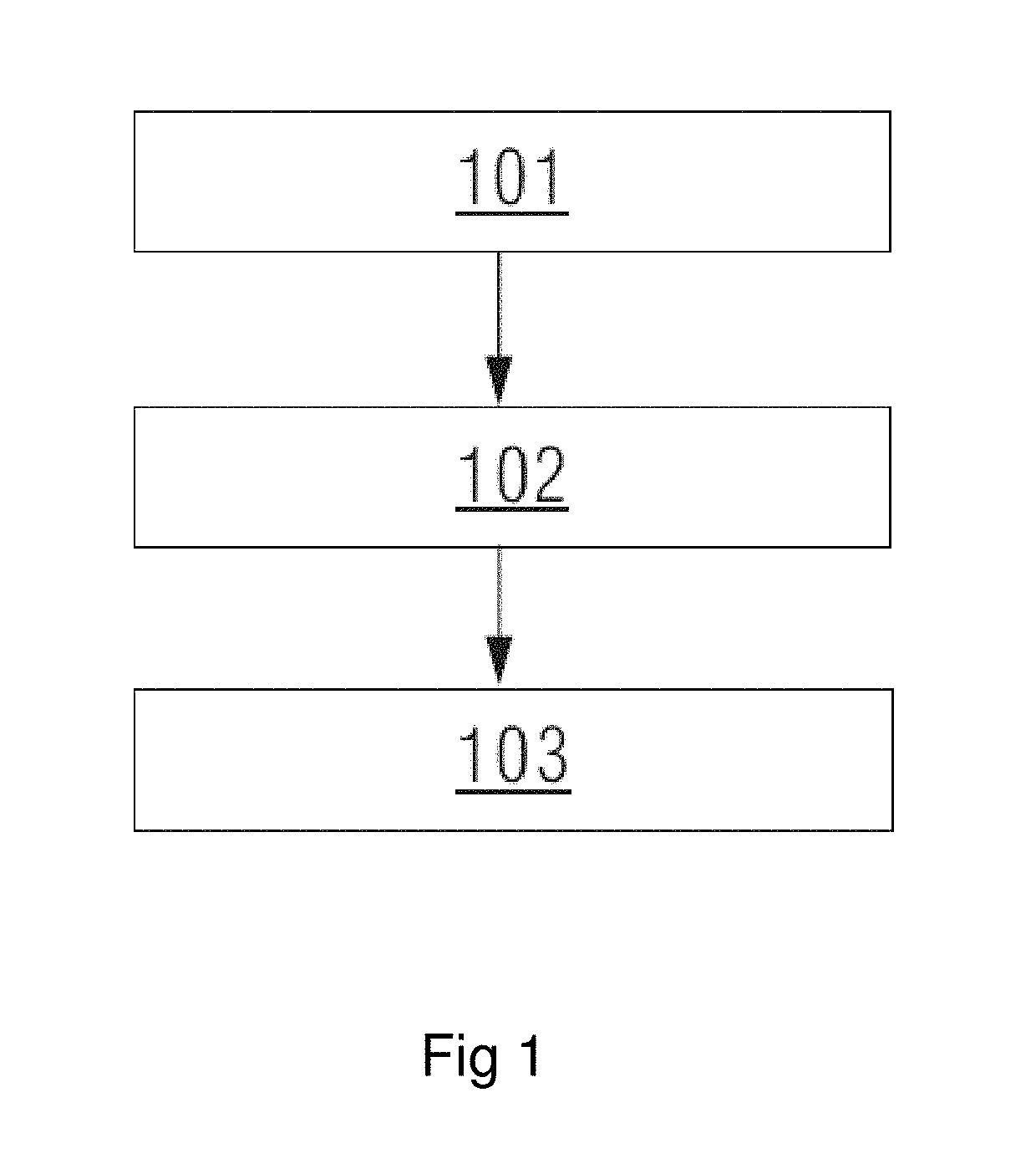
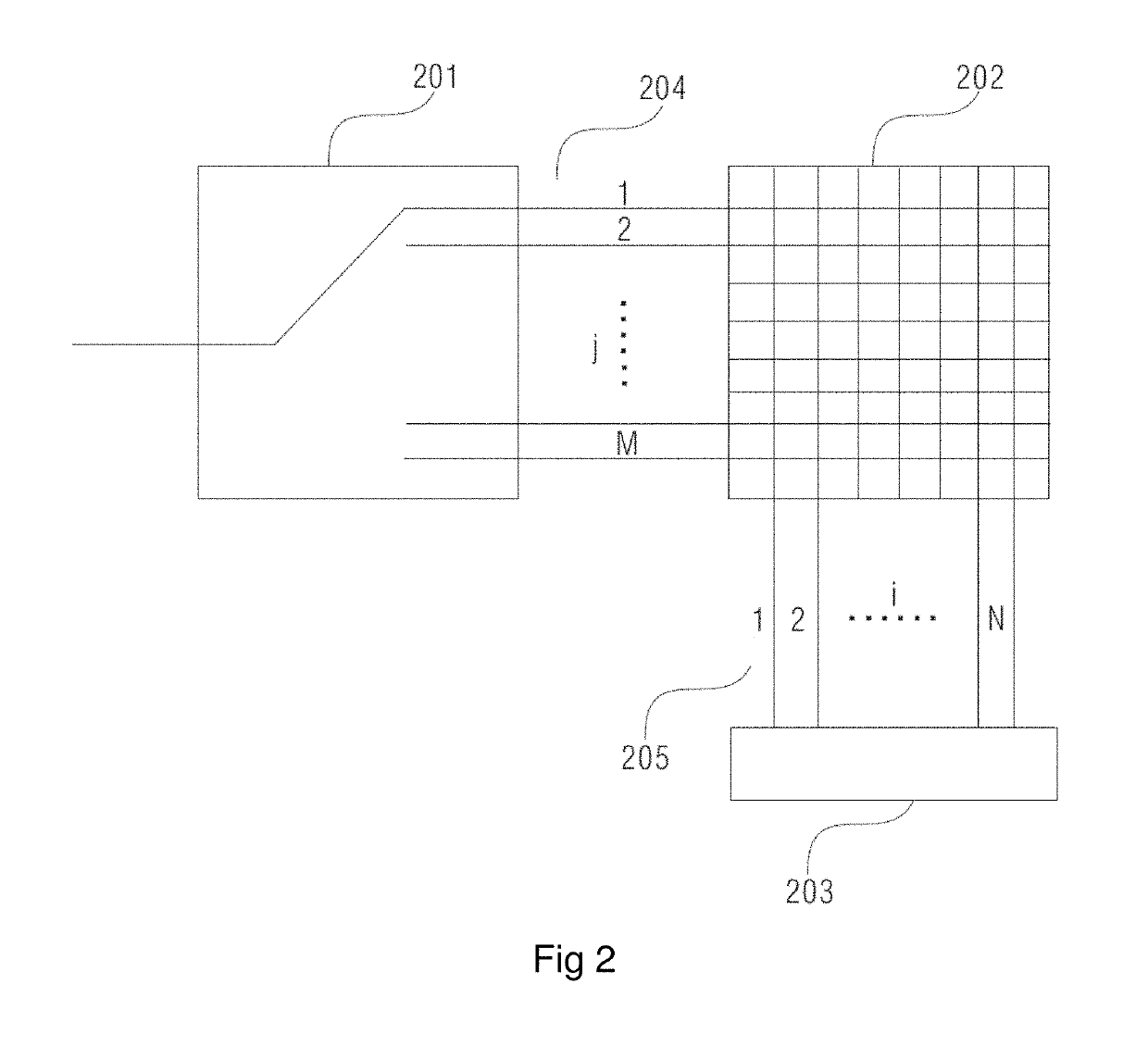
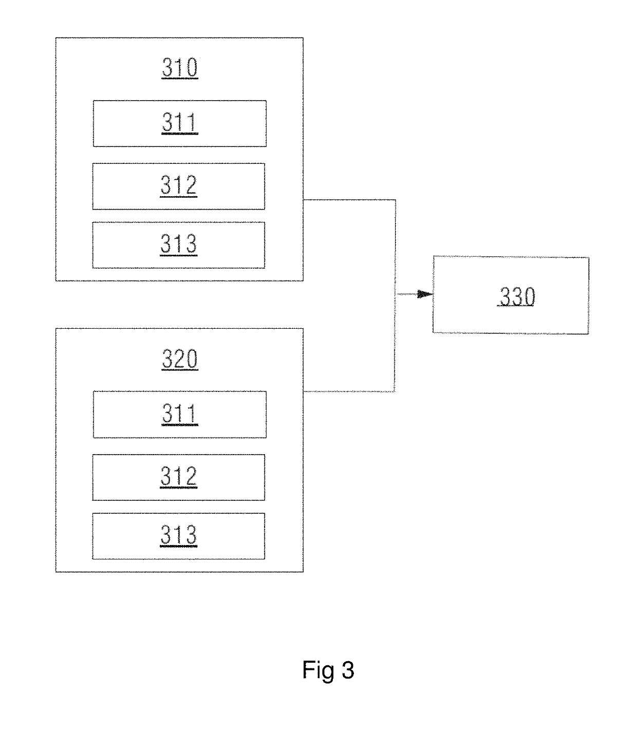
[0102]FIG. 1 is a demonstrative method flow chart of a phase deviation acquisition method in an embodiment of the present invention. FIG. 2 is a simplified model diagram of measurement of phase deviation in a magnetic resonance system in an embodiment of the present invention. FIG. 3 is a demonstrative module structural diagram of a phase deviation acquisition system in an embodiment of the present invention. Referring to FIGS. 1 to 3, a phase deviation acquisition method of an embodiment of the present invention is explained in detail.

[0103]In an embodiment of the present invention, a simplified model of phase deviation in an MR system comprises a coil unit 201, a coil channel selector 202, an analog receiver 203, an input channel 204 for communication between the coil unit 201 and the coil channel selector 202, and an output channel 205 for communication between the coil channel selector 202 and the analog receiver 203.

[0104]The coil unit 201 is used for receiving a system signal;...


PUM


Abstract

A digital mode matrix phase calibration includes acquiring an actual phase deviation θ′mn forming an actual phase deviation matrix θ′ of a factory system; calculating an ideal phase deviation forming an ideal phase deviation matrix; calculating a phase deviation of the actual phase deviation and the ideal phase deviation; acquiring a maximum value of the phase deviation; when the maximum value Δθmax is less than a preset threshold δ, calculating a field system phase deviation θ″mn, and a field system phase deviation matrix θ″ formed by the field system phase deviation θ″mn subjecting a field system to phase calibration. By acquiring only one row and one column in the phase deviation matrix, the technical solution in embodiments of the present invention can fit phase deviations of other rows and columns, and the method subjects the system to phase calibration quickly.

Description

BACKGROUND OF THE INVENTIONField of the Invention[0001]The present invention relates to a phase calibration method, in particular a magnetic resonance (MR) signal spatial phase calibration method.Description of the Prior Art[0002]Digital mode matrices are already widely used in the new generation of magnetic resonance systems. Compared with conventional hardware mode matrix technology, this new digital mode matrix technology does not require any change in coil hardware design. A digital mode matrix realizes the same signal conversion as a hardware mode on software; however, since the phase delay from magnetic resonance signal reception to completion of analog receiver sampling is different for each unit of a coil, it is necessary to calibrate the different delays.[0003]An existing phase calibration method is based on taking measurements when a system is installed, but such a method is time-consuming. For example, when it is necessary to recalibrate phase data because a specific syst...

Claims


Application Information

Patent Timeline
Patent Type & Authority Applications(United States)
IPC IPC(8): G01R33/58
CPCG01R33/583G01R33/3664G01R33/5659
Inventor HE, JIN QIANGKUANG, BINZHAO, JING
Owner SIEMENS HEALTHCARE GMBH
Why Eureka
Try Eureka