Polarity-Inverting Telecommunication Tap

a technology of polarity inverting and telecommunications taps, applied in the field of telecommunication, can solve the problems of inability to provide such rf services, time-consuming and laborious, and high cost of balancing by installing nodes in subscriber-dense areas

Active Publication Date: 2019-04-04
PCT INT
View PDF0 Cites 8 Cited by
  • Summary
  • Abstract
  • Description
  • Claims
  • Application Information

AI Technical Summary

Problems solved by technology

The provision of such RF services is inherently limited by the physical hardware the cable operator installs and controls.
However, this task is difficult and not always accurate.
However, later node balancing by installing nodes in subscriber-dense areas is time- and labor-intensive and expensive, and most cable operators resist it.
Many CATV devices are preferably uni-directional, and this reversal can cause performance issues, especially in passive devices.
However, simply physically flipping a device often is not a solution because of the dedicated footprint of the existing device; the footprints of many CATV devices are keyed and asymmetric, meaning they cannot simply be flipped or rotated.
Further, flipping a device is expensive, as it usually requires cuts and splices to be made.
This is expensive and breaks lines which are in known working order.

Method used


Image

  • Polarity-Inverting Telecommunication Tap
  • Polarity-Inverting Telecommunication Tap
  • Polarity-Inverting Telecommunication Tap

Examples


Embodiment Construction

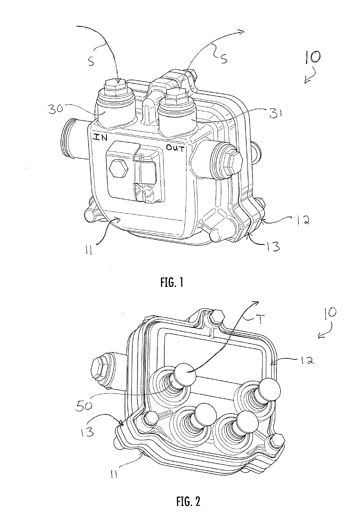
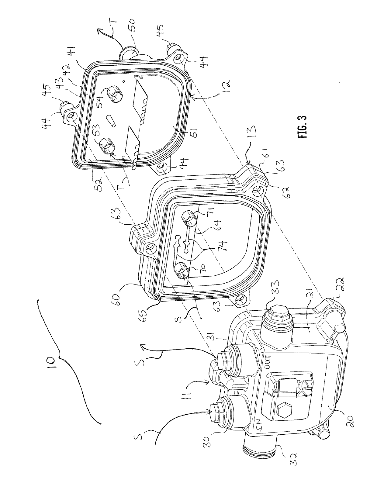
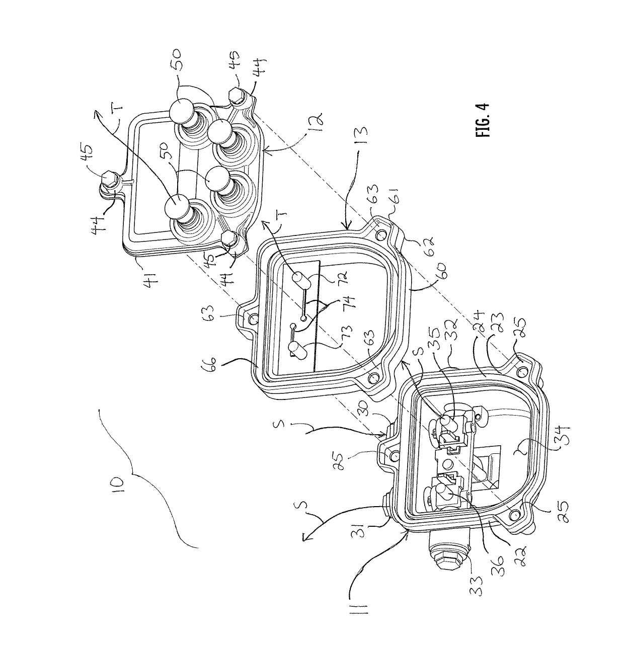
[0013]Reference now is made to the drawings, in which the same reference characters are used throughout the different figures to designate the same elements. FIGS. 1 and 2 illustrate a telecommunication tap 10. The tap 10 includes a backplate 11, an opposed faceplate 12, and an adapter plate 13 disposed therebetween. The adapter plate 13 is useful for inverting the polarity or directionality of a CATV signal S within the tap 10, so as to allows subscriber CATV devices connected to the tap 10 to function with correct polarity, despite the presence of a node split upstream from the tap 10.

[0014]Referring primarily now to FIGS. 3 and 4, the backplate 11 has two sets of coaxial cable posts for connecting the tap 10 to a telecommunication line such as a feeder cable or hard line. The backplate 11 shown here has a well-known footprint or form factor with a flat top, flat sides, and a curved bottom. This is one of four primary form factors most prominent in the industry, though this invent...


PUM


Abstract

A polarity-inverting telecommunication tap includes a backplate having an input port, an output port, and terminal posts. The input and output ports communicate a signal having a signal polarity. The tap also includes a faceplate having a tap port and having sockets corresponding and complemental to the terminal posts. The tap port communicates a tap signal having a tap signal polarity. The tap further includes an adapter plate disposed between the backplate and faceplate. The adapter plate has an electrical circuit which inverts the tap signal polarity with respect to the signal polarity, so that downstream CATV devices may operate with an intended polarity.

Description

CROSS-REFERENCE TO RELATED APPLICATIONS[0001]This application claims the benefit of U.S. Provisional Application No. 62 / 566,837, filed Oct. 2, 2017, all of which are hereby incorporated by reference.FIELD OF THE INVENTION[0002]The present invention relates generally to telecommunication, and more particularly to passive CATV devices.BACKGROUND OF THE INVENTION[0003]Radio frequency (“RF”) communications, such as cable TV (“CATV”) and internet services, are delivered to subscribers through lines and cables. Major cable operators have hybrid fiber coaxial (“HFC”) architecture in which a fiber optic line runs from an upstream source, such as the plant or headend, to a downstream local node. At the node, the fiber optic line is coupled to coaxial cables which eventually connect individual subscribers to RF services.[0004]The provision of such RF services is inherently limited by the physical hardware the cable operator installs and controls. Cable operators attempt to forecast technology...

Claims


Application Information

Patent Timeline
Patent Type & Authority Applications(United States)
IPC IPC(8): H01R12/51H01R13/512H01R31/06H01R12/71
CPCH01R12/515H01R13/512H01R31/06H01R12/718H01R31/065H01R2201/18
Inventor WILSON, BRANDONLIN, KANG
Owner PCT INT
Why Eureka
Try Eureka