Safety monitoring and control system and methods for a legged mobility exoskeleton device

a technology of safety monitoring and control system, which is applied in the direction of programmable control manipulators, chiropractic devices, physical therapy, etc., can solve the problems of restricting the state of the exoskeleton, and achieve the effect of preventing state transition and continuing temperature increas

Active Publication Date: 2019-04-11
EKSO BIONICS HLDG INC
View PDF11 Cites 25 Cited by
  • Summary
  • Abstract
  • Description
  • Claims
  • Application Information

AI Technical Summary

Benefits of technology

[0019]Device Standby is a control method that prevents accidental state transitions that may result in user instability or a fall. The exemplary embodiment related to Device Standby may include preventing unwanted transitions between the major mobility modes (e.g. stand, walk, sit) when the user manually puts the device into standby using a user interface, such as for example by short presses of the power buttons after the device has been turned on. Unwanted transitions among other modes (e.g. stair climbing), or states within a given mode (e.g. left step, right step), may be prevented either additionally or alternatively to prevent transitions between the major mobility modes. Furthermore, device standby may occur automatically or in response to other stimulus. While conventional configurations described in the background section suggest restricting device state based on center of pressure variation, the device standby method described herein, in which standby is volitional or based on other criteria, is not taught by prior configurations.
[0021]Device Alerts for Thermal Protection is a control method by which elevated temperatures are detected and utilized to modify device behavior to better protect the user and exoskeleton device components should elevated temperatures occur. The exemplary embodiment related to Thermal Protection may include limiting commanded current or torque in proportion to temperature levels, either continuously or in stages, such that continued temperature increase is less likely. Beyond a certain temperature threshold, the sit-to-stand (standing) and step-to-step (walking) mobility mode transitions may be disallowed, meaning that the user may only stand from walking, or sit from standing, to allow the actuators to cool. For enhanced safety, these effects may not be immediate. For example, the user must come to a stand or sit before current levels are correspondingly reduced to prevent disruption of a transition that is occurring and not yet complete. Beyond a certain higher temperature threshold, all motion may be prohibited, although a minimal level of current still may be available to provide some level of support. The thermal protection method described herein, in which temperatures affect device behavior in general, is not taught by prior configurations.

Problems solved by technology

In addition, the safety control methods described herein do restrict which exoskeleton states may be reached.

Method used


Image

  • Safety monitoring and control system and methods for a legged mobility exoskeleton device
  • Safety monitoring and control system and methods for a legged mobility exoskeleton device
  • Safety monitoring and control system and methods for a legged mobility exoskeleton device

Examples


Embodiment Construction

[0043]Embodiments of the present invention will now be described with reference to the drawings, wherein like reference numerals are used to refer to like elements throughout. It will be understood that the figures are not necessarily to scale.

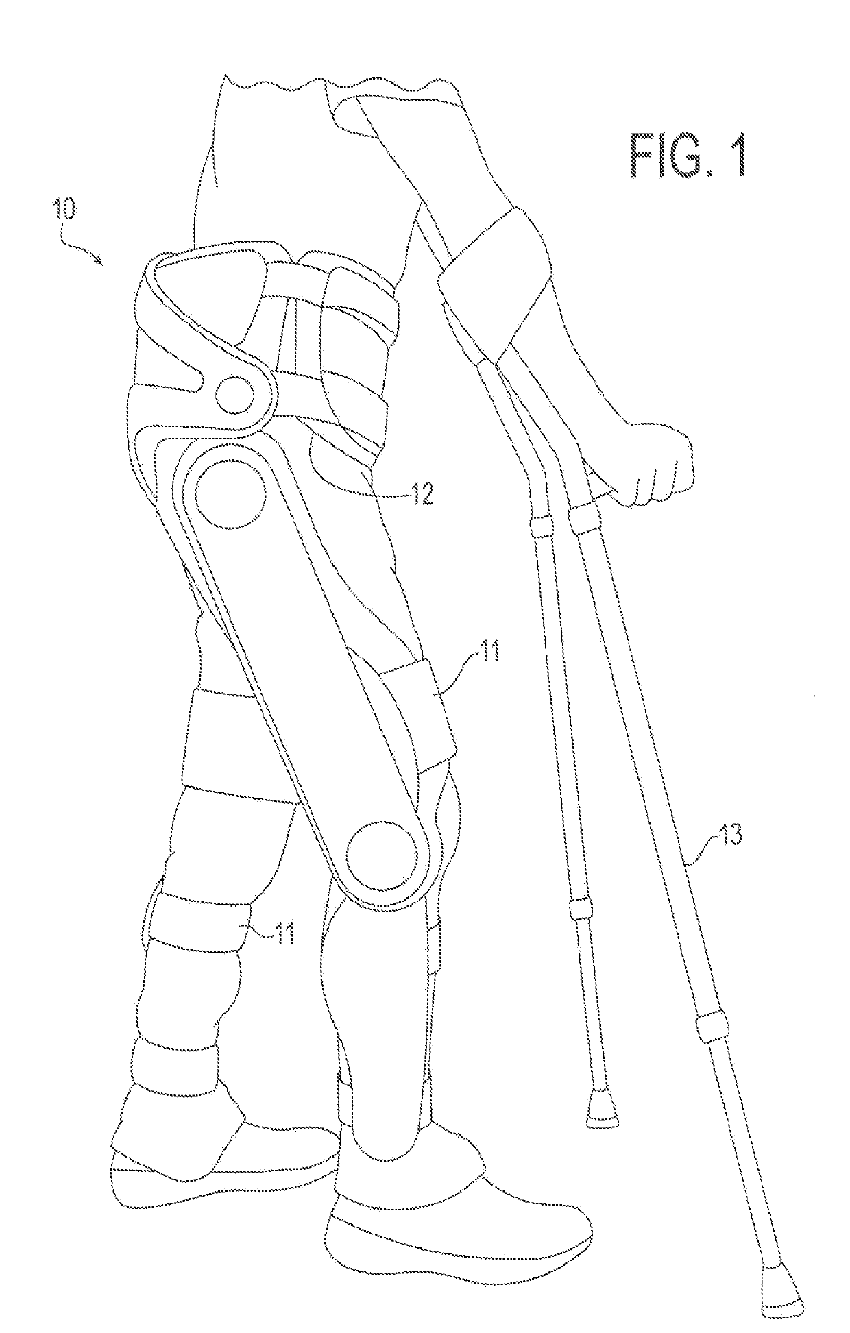
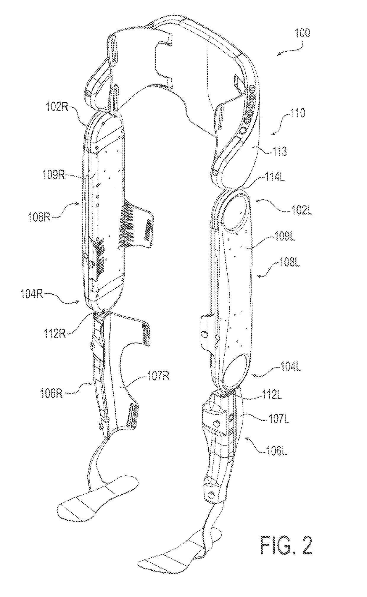
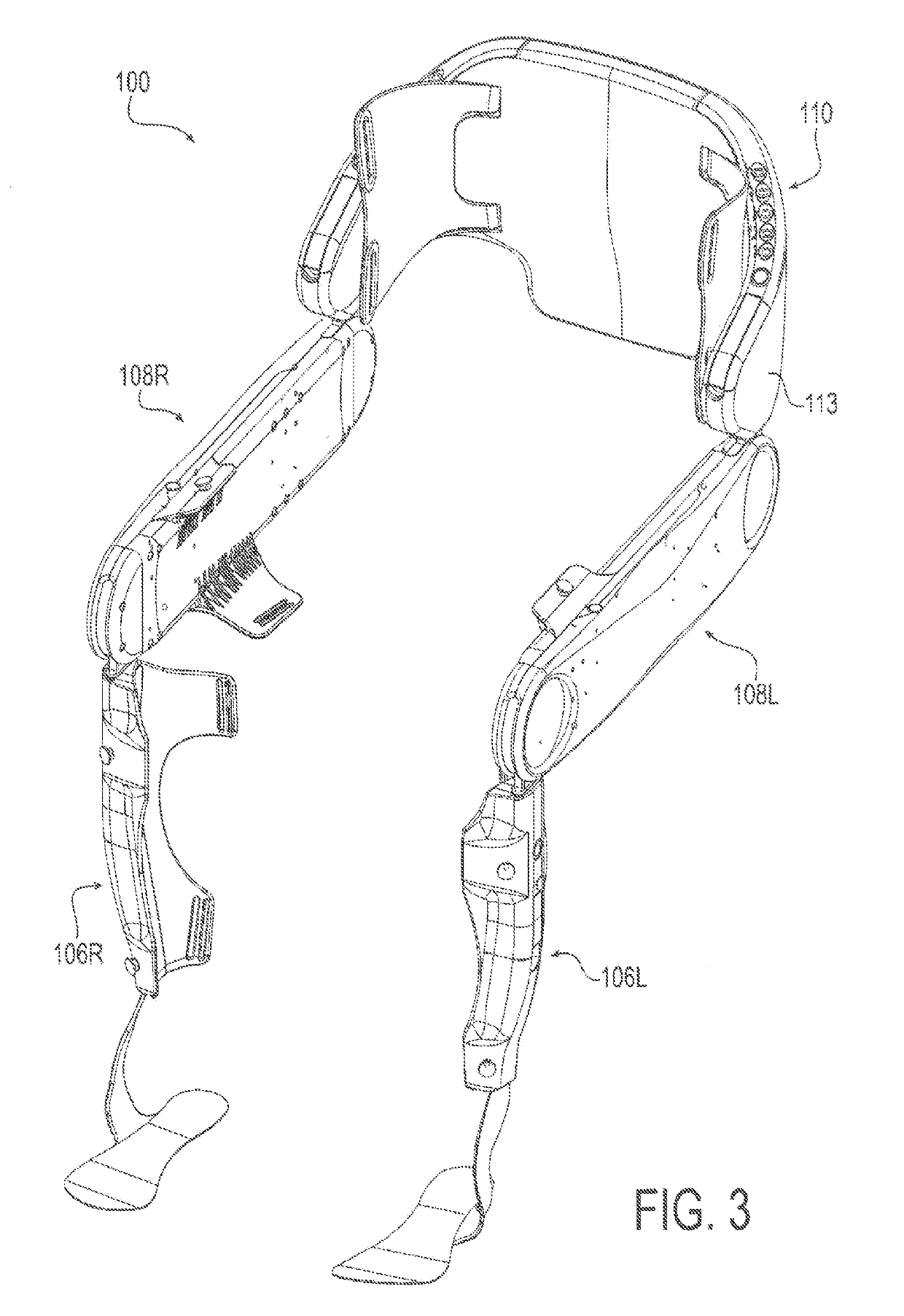
[0044]For context, FIGS. 1-13 depict various views of an exemplary exoskeleton device that may be used in connection with the control system and methods of the present invention. A somewhat generalized description of such exoskeleton device is provided here for illustration purposes. A more detailed description of such device may be found in Applicant's International Patent Appl. No. PCT / US2015 / 023624 filed on Mar. 3, 2015, which is incorporated here in its entirety by reference. It will be appreciated, however, that the described exoskeleton device presents an example usage, and that the control system and methods of the present invention are not limited to any particular configuration of an exoskeleton device. Variations may be made to the e...


PUM


Abstract

A method of controlling a mobility device and related device including at least one drive component that drives at least one joint component is described. The control method may include executing a control application with an electronic controller to perform: receiving sensor information from sensors corresponding to a state and / or mode of the mobility device; analyzing the sensor information and determining a control mode of operation based on the sensor information; generating a control signal to output an alert via electronic indicators corresponding to the determined control mode; and controlling at least one drive component of the mobility device to selectively configure and modulate at least one joint component in accordance with the determined control mode of operation. Different alerts may be outputted by the electronic indicators depending on the nature or severity of the alert condition, accompanied by respective device control operations in accordance with the alert condition.

Description

RELATED APPLICATIONS[0001]This application claims the benefit of U.S. Provisional Application No. 62 / 266,840 filed Dec. 15, 2015, which is incorporated herein by reference.FIELD OF INVENTION[0002]The present invention relates to electronic control systems for a legged mobility device or “exoskeleton” device, including control systems for safety monitoring of the operation of the legged mobility device or exoskeleton device.BACKGROUND OF THE INVENTION[0003]There are currently on the order of several hundred thousand spinal cord injured (SCI) individuals in the United States, with roughly 12,000 new injuries sustained each year at an average age of injury of 40.2 years. Of these, approximately 44% (approximately 5300 cases per year) result in paraplegia. One of the most significant impairments resulting from paraplegia is the loss of mobility, particularly given the relatively young age at which such injuries occur. Surveys of users with paraplegia indicate that mobility concerns are ...

Claims


Application Information

Patent Timeline
Patent Type & Authority Applications(United States)
IPC IPC(8): B25J9/16A61H3/00B25J9/00
CPCB25J9/1674A61H3/00B25J9/1615B25J9/0006G05B2219/40305G05B2219/23172A61H1/024A61H2201/5058
Inventor DALLEY, SKYLER ASHTONFARRIS, RYANETHERIDGE, STEVENMORRISON, SCOTTMURRAY, SPENCER
Owner EKSO BIONICS HLDG INC
Why Eureka
Try Eureka