Touch display device, microcontroller, and driving method

a technology of touch display device and microcontroller, which is applied in the direction of generating/distributing signals, circuit optical details, instruments, etc., can solve problems such as degrading touch sensing performan

Active Publication Date: 2019-12-19
LG DISPLAY CO LTD
View PDF1 Cites 10 Cited by
  • Summary
  • Abstract
  • Description
  • Claims
  • Application Information

AI Technical Summary

Benefits of technology

[0007]Various aspects of the present disclosure provide a touch display device, a microcontroller, and a driving method, able to prevent unnecessary parasitic capacitance from being generated between touch electrodes, to which a driving signal is applied for touch sensing, and other surrounding electrodes.
[0008]Also provided are a touch display device, a microcontroller, and a driving method, able to prevent a phase difference between a touch electrode driving signal and a variety of other pulse signals in the case of panel driving for touch sensing.
[0009]Also provided are a touch display device, a microcontroller, and a driving method, able to simultaneously perform display processing and touch sensing, and in the case of driving for the display processing and the touch sensing, prevent phase differences among a variety of pulses generated by a display panel, a printed circuit board (PCB), etc.

Problems solved by technology

Such unnecessary parasitic capacitance may degrade touch sensing performance, which is problematic.

Method used


Image

  • Touch display device, microcontroller, and driving method
  • Touch display device, microcontroller, and driving method
  • Touch display device, microcontroller, and driving method

Examples


case 1

[0194]Case 1 and Case 2 are driving cases during the active period. Case 3 is a driving case during the blank period.

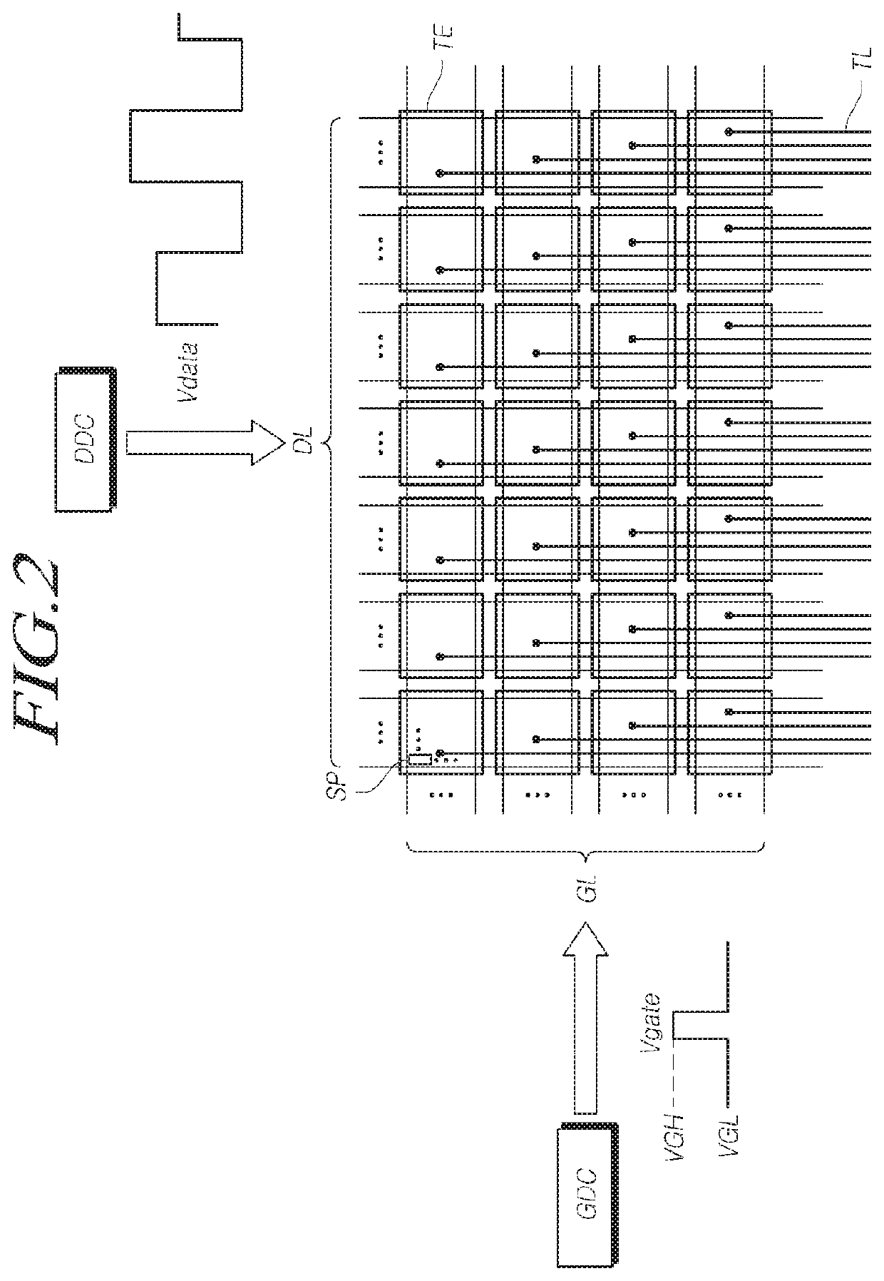
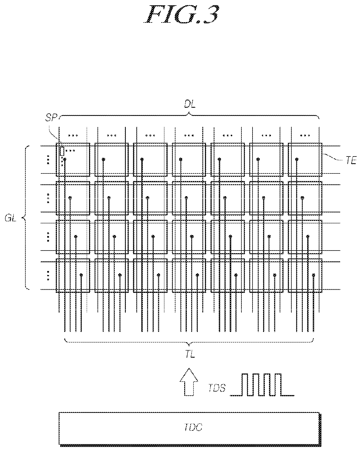
[0195]An off-level gate voltage VGL and an on-level gate voltage VGH supplied to the gate driver circuit GDC to generate the touch electrode driving signal TDS applied to the touch electrodes TE, the data signal Vdata applied to the data lines DL, and the scan signal Vgate applied to the gate lines will be described with respect to the above-described three cases.

[0196]In Case 2 in which only the display driving is performed during the active period, the touch electrode driving signal TDS applied to the touch electrodes TE corresponds to the second touch electrode driving signal TDS2 in the form of a DC voltage.

[0197]The data signal Vdata applied to the data lines DL is a signal corresponding to an analog image signal obtained by digital-analog converting a digital image signal for the display processing. The data signal Vdata may be a pixel voltage applied to a pixel...


PUM


Abstract

A touch display device, a microcontroller, and a driving method. During touch driving, no phase difference is generated among a plurality of pulse signals generated by a display panel, a printed circuit board, etc. Unnecessary parasitic capacitance is prevented from occurring between a touch electrode, to which a touch-sensing driving signal is applied, and surrounding other electrodes. Touch sensing performance is improved, and display performance is improved.

Description

CROSS REFERENCE TO RELATED APPLICATION[0001]This application claims priority to Korean Patent Application No. 10-2018-0068114, filed Jun. 14, 2018, which is hereby incorporated by reference for all purposes as if fully set forth herein.BACKGROUNDTechnical Field[0002]Exemplary embodiments relate to a touch display device, a microcontroller, and a driving method.Description of Related Art[0003]With the development of the information society, there has been an increasing demand for image display devices. In this regard, a range of display devices, such as liquid crystal display (LCD) devices, plasma display devices, and organic light-emitting diode (OLED) display devices, have recently come into widespread use.[0004]Among such display devices, touch display devices provide touch-based user interfaces enabling users to intuitively and conveniently input data or instructions directly to devices, rather than using conventional data input systems, such as buttons, a keyboard, or a mouse.[0...

Claims


Application Information

Patent Timeline
Patent Type & Authority Applications(United States)
IPC IPC(8): G06F3/044H05K1/02G06F1/10
CPCG06F3/0443H05K1/0274G06F1/10G06F3/0416G06F3/04184G06F3/0412
Inventor KANG, SEONGKYUKIM, SUNGCHULKIM, HOONBAEKIM, SUNYEOP
Owner LG DISPLAY CO LTD
Why Eureka
Try Eureka