Camshaft phaser using both cam torque and engine oil pressure
a camshaft and torque technology, applied in the direction of machines/engines, valve details, valve arrangements, etc., can solve the problems of reducing the torque energy of the camshaft at high engine rpm, limiting the performance of the ta phaser in relation to the engine oil supply,
- Summary
- Abstract
- Description
- Claims
- Application Information
AI Technical Summary
Benefits of technology
Problems solved by technology
Method used
Image
Examples
first embodiment
[0035]FIGS. 4-6 show a variable cam timing phaser of a first embodiment with a control valve including recirculation check valves and spool dependent variable venting.
[0036]Internal combustion engines have employed various mechanisms to vary the angle between the camshaft and the crankshaft for improved engine performance or reduced emissions. The majority of these variable camshaft timing (VCT) mechanisms use one or more “vane phasers” on the engine camshaft (or camshafts, in a multiple-camshaft engine). In most cases, the phasers have a rotor assembly 205 with one or more vanes 204, mounted to the end of the camshaft (not shown), surrounded by a housing assembly 200 with the vane chambers into which the vanes fit. It is possible to have the vanes 204 mounted to the housing assembly 200, and the chambers in the rotor assembly 205, as well. The housing's outer circumference 201 forms the sprocket, pulley or gear accepting drive force through a chain, belt, or gears, usually from the...
second embodiment
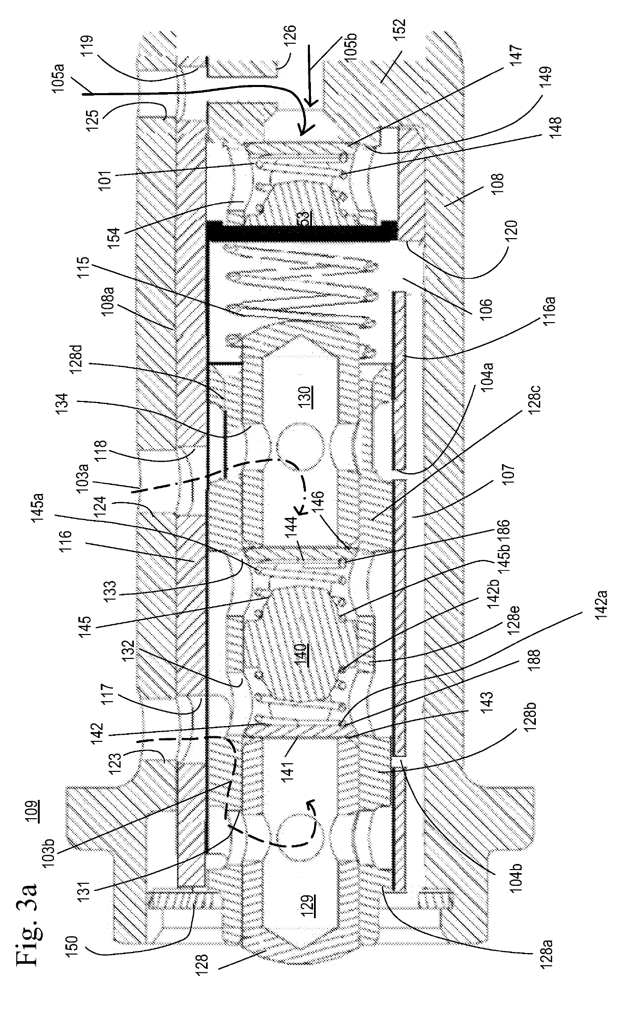
[0065]FIGS. 7-9 show a variable cam timing phaser of a second embodiment with a control valve including recirculation check valves, constant, continuous venting, and variable venting. FIGS. 11a and 11b show the corresponding control valve 309.
[0066]The difference between the phaser of the first embodiment shown in FIGS. 4-6 and the phaser of the second embodiment is the additional continuous vents 104d and 104c present in the present in the sleeve 116.
[0067]Referring to FIG. 11a and 11b, a control valve 309 has a center bolt body 108 defining a center bolt bore 108a. Within the bore 108a of the center bolt body 108 is a protrusion 152. The center bolt body 108 has a series of center bolt ports 123, 124, 125, 126. The bore 108a of the center bolt body 108 receives a sleeve 116. The sleeve 116 is fixed within the bore 108a between a washer or retaining ring 150 and the center bolt body protrusion 152. The sleeve 116 has a plurality of sleeve ports 117, 118, 119, 120 and vents 104a, 10...
third embodiment
[0093]FIG. 10 shows a phaser of a third embodiment is similar to the embodiment shown in FIGS. 4-6, but with an additional spool dependent variable vent added to the sleeve and opened when the phaser is moving toward an advance position (spool full out position). The additional spool dependent variable vent only vents at the spool out condition. The additional spool dependent variable vent allows for additional venting to increase the time and rotation the lock pin 225 to engage the recess 227 and moving to the lock position.
[0094]The duty cycle is adjusted to a range of 0-50% the force of the VFS 206 on the spool 128 is changed and the spool 128 is moved to the left in an advance mode in the figure by spring 115, until the force of the VFS 206 balances the force of the spring 115. Fluid exits from the retard chamber 203 through the retard line 213 to the second center bolt port 124 and the second sleeve port 118. From the second sleeve port 118, fluid flows between spool lands 128c...
PUM
 Abstract
Description
Claims
Application Information
 - R&D
- Intellectual Property
- Life Sciences
- Materials
- Tech Scout
- Unparalleled Data Quality
- Higher Quality Content
- 60% Fewer Hallucinations
Browse by: Latest US Patents, China's latest patents, Technical Efficacy Thesaurus, Application Domain, Technology Topic, Popular Technical Reports.
© 2025 PatSnap. All rights reserved.Legal|Privacy policy|Modern Slavery Act Transparency Statement|Sitemap|About US| Contact US: help@patsnap.com


