Pyrolytic oven with a lighting module

a technology of lighting module and pyrolysis oven, which is applied in the direction of heating fuel, heating/cooling arrangements, domestic heating details, etc., can solve the problems of reduced lighting intensity and service life, and the risk of pyrolysis mode lamps being exposed to particularly high temperatures, so as to avoid overheating

Active Publication Date: 2019-04-11
EMZ HANAUER
View PDF2 Cites 1 Cited by
  • Summary
  • Abstract
  • Description
  • Claims
  • Application Information

AI Technical Summary

Benefits of technology

[0005]It is an object of the present invention to provide a pyrolytic oven that avoids overheating of a light source used therein to illuminate a cooking chamber.
[0006]The present invention achieves these and other objectives by providing a pyrolytic oven having a housing and a muffle delimiting a cooking chamber inside the housing. A muffle interior forming the cooking chamber is preferably accessible via an oven door mounted on the housing, which door is used to close the muffle. Between the housing and the muffle, the oven is provided with a gap for the thermal separation of the muffle from the housing. The oven further comprises a fan device, which is configured and controlled to generate an air flow in the gap. In this way a heat input into the housing induced by the muffle can be limited and thus excessive heating of the housing can be prevented.

Problems solved by technology

However, the use of light-emitting diodes calls for effective heat management, as their lighting intensity and service life decrease with increasing temperatures.
Lamps used in a pyrolytic oven run the risk in pyrolytic mode of being exposed to particularly high temperatures, which is a problem for the use of light-emitting diodes in particular.

Method used


Image

  • Pyrolytic oven with a lighting module
  • Pyrolytic oven with a lighting module
  • Pyrolytic oven with a lighting module

Examples


Embodiment Construction

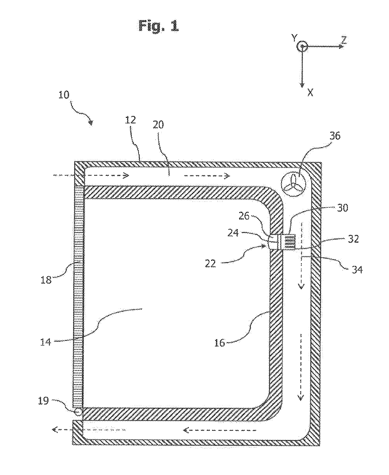
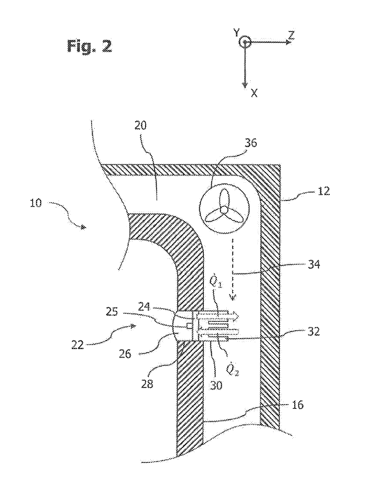
[0028]A pyrolytic oven 10 shown in FIG. 1 comprises a housing 12 and a muffle 16 delimiting a cooking chamber 14 inside the housing 12. The muffle 16 is accessible via an oven door 18 mounted on the housing 12, which door is mounted pivotably on the housing 12 about a horizontal shaft 19 between a position closing the cooking chamber 14 and a position releasing the latter. The oven door 18 is provided with a viewing window, through which a user can look into the cooking chamber 14. The oven 10 further comprises a control unit, which is not shown here and which executes control functions of the oven 10 and is preferably accommodated above the muffle 16 and inside the housing 12. The oven 10 is provided with a gap 20 between the housing 12 and the muffle 16.

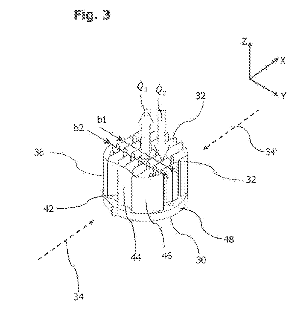
[0029]A lighting module 22 of the oven 10 is used to illuminate the cooking chamber 14 and is inserted into a wall section of the muffle 16. The lighting module 22 comprises at least one circuit board 24, on the front side of which...


PUM


Abstract

A pyrolytic oven comprises a housing and a muffle delimiting a cooking chamber inside the housing. A lighting module serves to illuminate the cooking chamber, wherein the lighting module has a cooling structure with an arrangement of cooling extensions formed in particular as pins or ribs, which project into a gap between housing and muffle and have a convection effect in a cooking mode of the oven. A fan device of the oven is configured and controlled to generate an air flow encountering the cooling structure in the gap in a pyrolytic mode of the oven. The cooling structure of the lighting module further has a wall formation, which in pyrolytic mode generates a wind shadow relative to the air flow for a number of cooling extensions of the cooling structure arranged distributed in a transverse plane to the flow direction of the air flow.

Description

BACKGROUND OF THE INVENTION1. Field of the Invention[0001]The present invention relates generally to a pyrolytic oven with a lighting module for illuminating a cooking chamber provided in the oven.2. Description of the Prior Art[0002]Ovens are generally used for the preparation of foods, which are cooked due to the effect of heat. In a cooking mode of the oven, temperatures of up to 300° C. are usually attained in a cooking chamber of the oven. To provide a self-cleaning function it is further known to operate the oven in another operating mode, in which cleaning of the cooking chamber takes place by means of pyrolysis. In this case the temperature in the cooking chamber is increased to up to 500° C., due to which pyrolytic decomposition of undesirable baking residues is achieved.[0003]Light-emitting diodes are used increasingly as lamps in ovens on account of their advantageous properties. Their energy density and efficiency, i.e. the proportion of converted light relative to the e...

Claims


Application Information

Patent Timeline
Patent Type & Authority Applications(United States)
IPC IPC(8): F24C14/02F24C7/06F24C9/00F24C15/00
CPCF24C14/02F24C7/062F24C9/00F24C15/006F24C15/008A47J37/06F21V33/0044F21V29/50F21V29/67F21Y2115/10
Inventor SIGNORINO, MANFREDISCHENKL, JOHANNBRABEC, MARTIN
Owner EMZ HANAUER
Why Eureka
Try Eureka