Simultaneous representation of moving and static obstacles for automatically controlled vehicles

a technology of automatic control and static obstacles, applied in the direction of process and machine control, image enhancement, instruments, etc., can solve the problems of inability to handle obstacle motion, inability to avoid/target both moving static obstacles and static obstacles in the prior art, and not offering a significant throughput advantage over hardware-based dense stereo techniques

Active Publication Date: 2019-04-11
CALIFORNIA INST OF TECH
View PDF0 Cites 11 Cited by
  • Summary
  • Abstract
  • Description
  • Claims
  • Application Information

AI Technical Summary

Benefits of technology

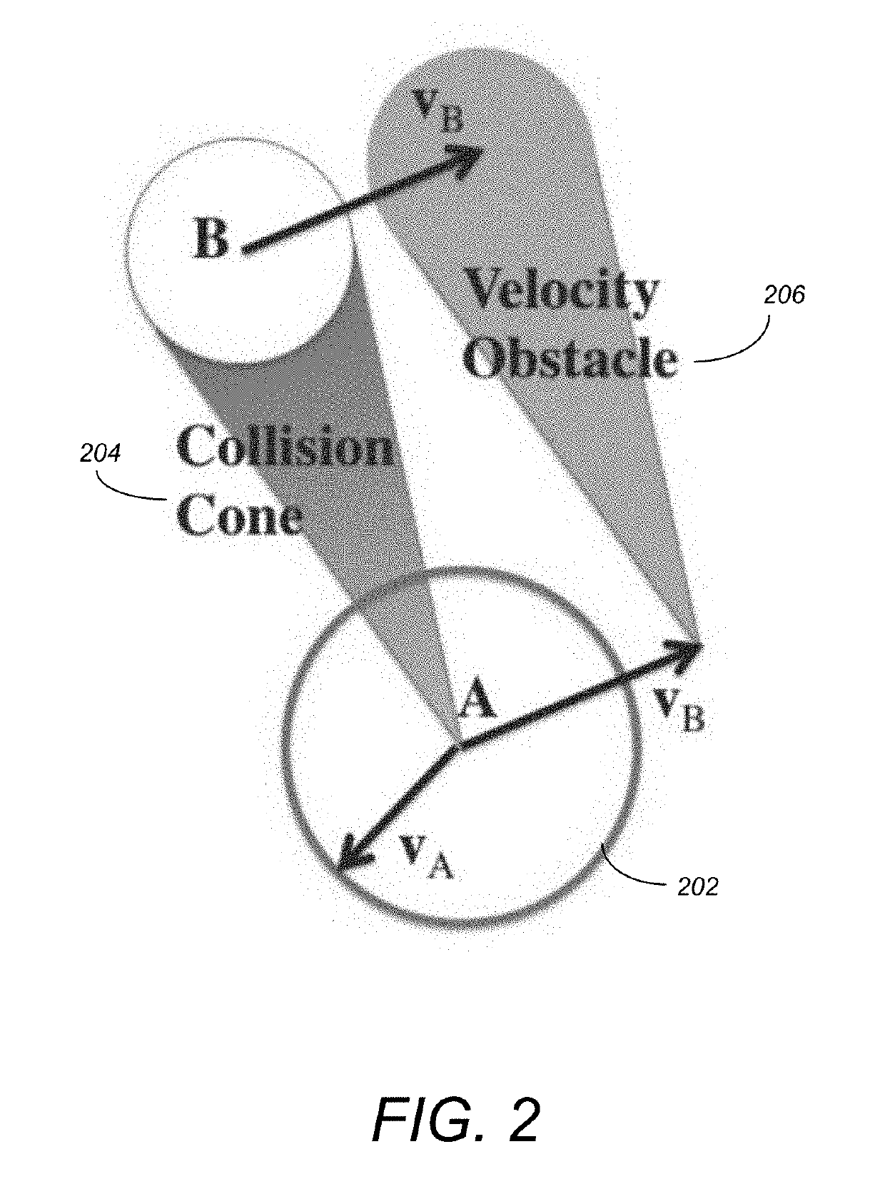
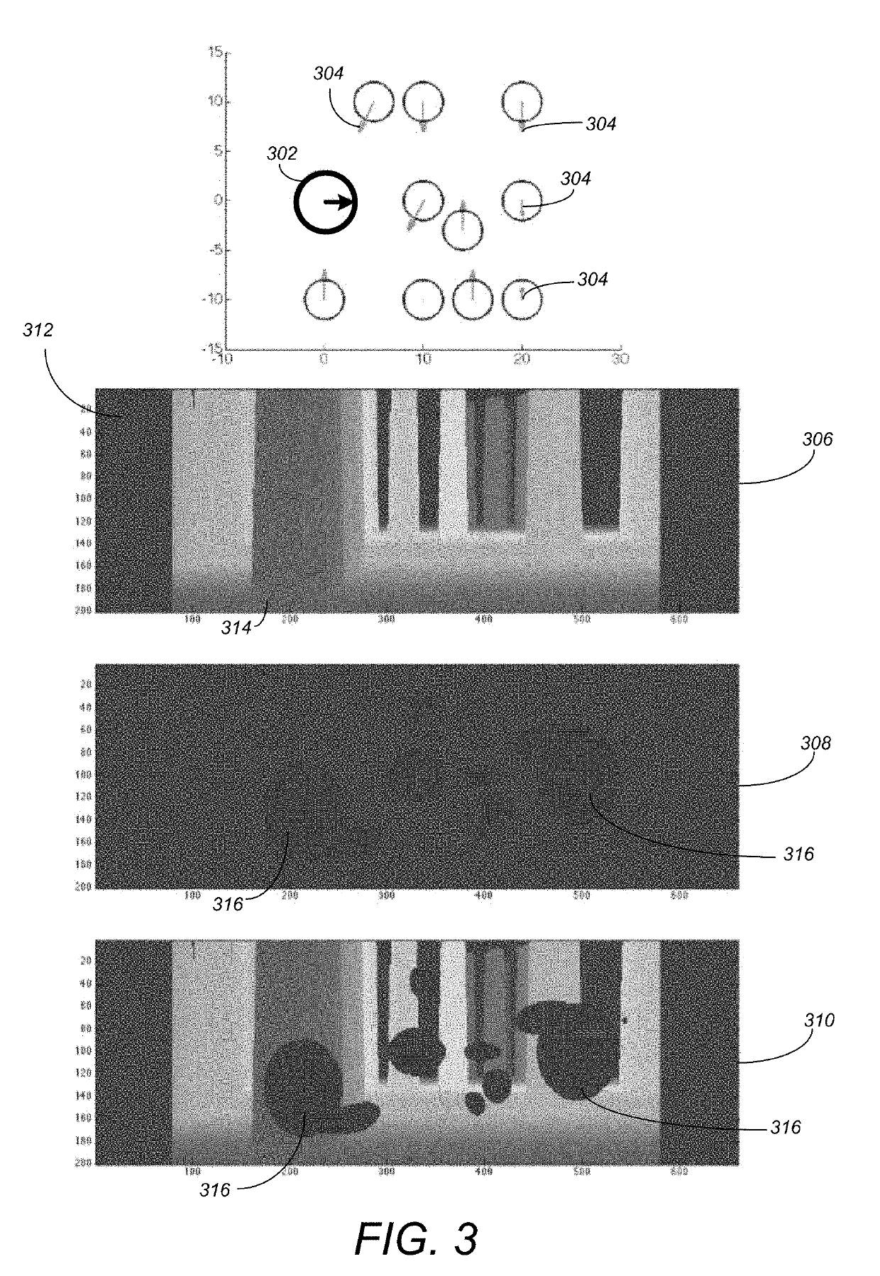
[0023]One or more embodiments of the invention provide a system, framework, and method for automatically controlling vehicles in environments containing static obstacles, moving obstacles, or both. Static obstacle data from onboard sensors or other externally sensed or broadcast sources are compactly represented, along with moving obstacle data from onboard sensors or other externally sensed or broadcast sources, in a data structure referred to as a combined representation. The combined representation con

Problems solved by technology

Prior art implementations are unable to avoid/target both moving and static obstacles.
This technique is able to achieve extremely high frame rates (120 frames per second), but blind to obstacles that are first encountered at a distance less than that of the detection horizon, cannot handle obstacle motion, and does not offer a significant throughput advantage over hardware-based dense stereo techniques.
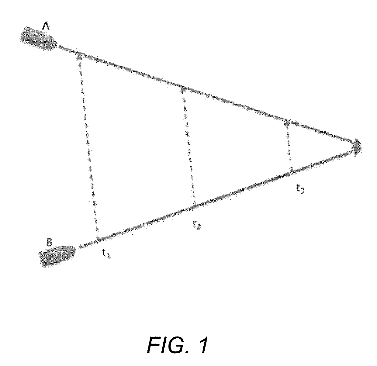
The representation of an environment for motion planning becomes considerably more challenging if moving and static obstacles occur simultaneously.
The addition of a time coordinate severely increases the computational expense and diff

Method used


Image

  • Simultaneous representation of moving and static obstacles for automatically controlled vehicles
  • Simultaneous representation of moving and static obstacles for automatically controlled vehicles
  • Simultaneous representation of moving and static obstacles for automatically controlled vehicles

Examples


Embodiment Construction

[0031]In the following description, reference is made to the accompanying drawings which form a part hereof, and which is shown, by way of illustration, several embodiments of the present invention. It is understood that other embodiments may be utilized and structural changes may be made without departing from the scope of the present invention.

Overview

[0032]One or more embodiments of the invention provide a pipeline for automatically controlling vehicles in two or three dimensions, such as robotic aircraft (including those of a small, portable size known as micro air vehicles, or MAVs) watercraft, and planar ground vehicles, in environments containing static obstacles, moving obstacles, or both simultaneously. Embodiments may be utilized in / by aircraft of the multirotor family, which include the widely available quadcopter platform (also referred to as a “quadrotor” or, colloquially, as a “drone”). Embodiments may be utilized in / by aircraft of the fixed-wing family, which includes...


PUM


Abstract

A method and system provide the ability to automatically control a vehicle to avoid obstacle collision. Range data of a real-world scene (including depth data to static objects) is acquired. Positions and velocities of moving objects are acquired. The range data is combined into an egospace representation for pixels in egospace that is specified with respect to a radially aligned coordinate system. An apparent size of the static objects is expanding, in the egospace representation, based on a dimension of the vehicle. A speed of the vehicle is specified. A velocity obstacle corresponding to the moving objects is constructed. A mask is created in the coordinate system and identifies candidate radial paths that will result in a collision between the vehicle and the moving objects. The mask is combined with the egospace representation that is then used to determine a path for the vehicle.

Description

CROSS-REFERENCE TO RELATED APPLICATIONS[0001]This application claims the benefit under 35 U.S.C. Section 119(e) of the following co-pending and commonly-assigned U.S. provisional patent application(s), which is / are incorporated by reference herein:[0002]Provisional Application Ser. No. 62 / 568,707, filed on Oct. 5, 2017, with inventor(s) Anthony T. Fragoso, entitled “Simultaneous Representation of Moving and Static Obstacles for Micro Air Vehicles,” attorneys' docket number 176.152-US-P1.[0003]This application is related to the following co-pending and commonly-assigned patent application, which application is incorporated by reference herein:[0004]U.S. patent application Ser. No. 15 / 394,647, filed on Dec. 29, 2016, with inventor(s) Anthony T. S. Fragoso, Larry H. Matthies, Roland Brockers, and Richard M. Murray, entitled “Controlling Unmanned Aerial Vehicles to Avoid Obstacle Collision,” attorneys' docket number 176.126-US-U1, which application claims the benefit of 62 / 274,924 filed...

Claims


Application Information

Patent Timeline
IPC IPC(8): G08G5/04G08G5/00B64C39/02G06T7/20G06T7/70
CPCG08G5/045G08G5/0069G08G5/0078B64C39/024G06T7/20G06T7/70G06T2207/30261B64C2201/141G05D1/0202G05D1/024G05D1/12G08G5/0021B64U2201/10
Inventor FRAGOSO, ANTHONY T.S.
Owner CALIFORNIA INST OF TECH
Why Eureka
Try Eureka