Elastic torsion element for connecting a rotor blade to a rotor hub of a rotor

a technology of rotor hub and rotor blade, which is applied in the direction of rotorcraft, vehicles, aircrafts, etc., can solve the problems of high manufacturing cost, complex and elaborate flexbeam elements, and high cost of composite components, so as to achieve easy manufacturing and low cost

Active Publication Date: 2019-04-18
AIRBUS HELICOPTERS DEUT GMBH
View PDF1 Cites 0 Cited by
  • Summary
  • Abstract
  • Description
  • Claims
  • Application Information

AI Technical Summary

Benefits of technology

[0012]It is, therefore, an object of the present invention to provide a new elastic torsion element for connecting a rotor blade to a rotor hub of a rotor. This new elastic torsion element should comprise an integrated elastic lead-lag hinge and should be manufacturable easily and at comparatively low cost.

Problems solved by technology

However, respective flexbeam elements are usually rather complex and consist of composite components that are very elaborate and difficult to manufacture.
Thus, these composite components are generally expensive.
However, such a cross-section is complicated and elaborate to manufacture and, consequently, expensive, and provides for a comparatively high lead-lag stiffness.
Furthermore, comparatively long lead-lag-soft regions are required, resulting in higher weight and lower aerodynamic performance of the flexbeams.
Such a large distance of the shear centers from the pitching resp. tortion axis nevertheless leads to a high torsional stiffness, especially when a centrifugal load is applied to the flexbeam.

Method used


Image

  • Elastic torsion element for connecting a rotor blade to a rotor hub of a rotor
  • Elastic torsion element for connecting a rotor blade to a rotor hub of a rotor
  • Elastic torsion element for connecting a rotor blade to a rotor hub of a rotor

Examples


Embodiment Construction

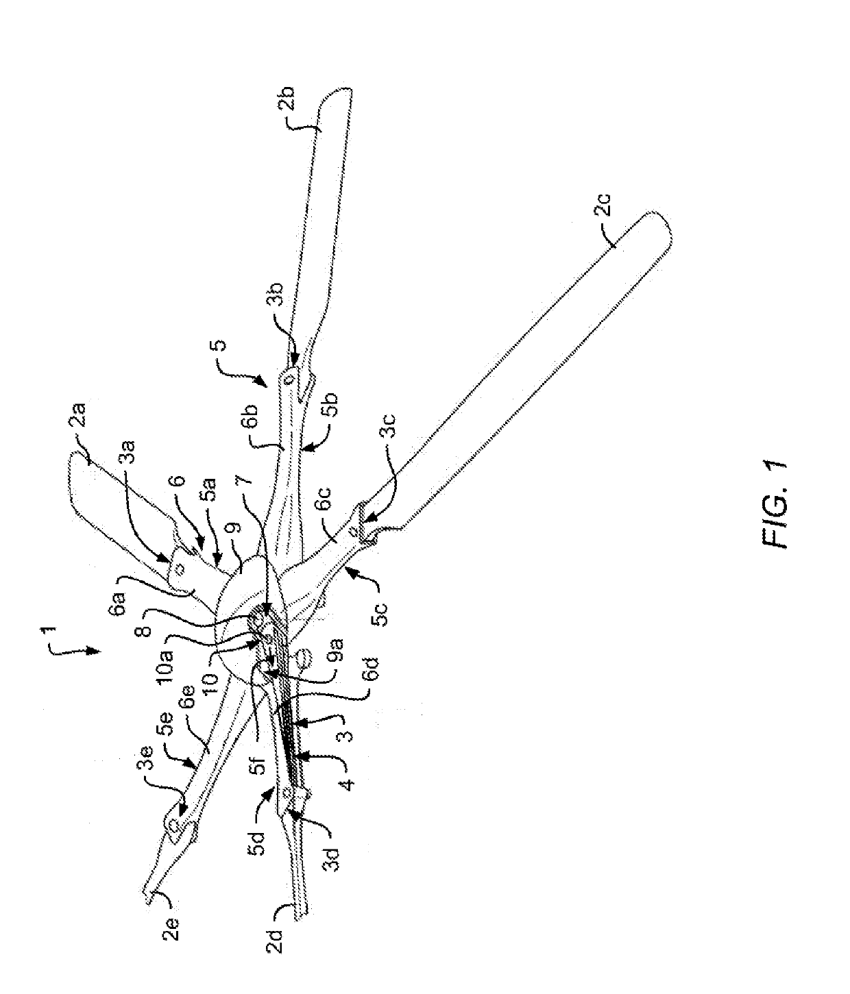
[0054]FIG. 1 shows a multi-blade rotor 1 of a rotary wing aircraft, in particular a multi-blade rotor for a main rotor of a helicopter. The multi-blade rotor 1 illustratively comprises a rotor shaft 8 that is embodied with a rotor hub 7. Furthermore, a rotor head covering cap 9 is provided for covering a central portion of the multi-blade rotor 1, which comprises the rotor hub 7 and which illustratively defines an associated rotor head. The rotor head covering cap 9 is shown with an illustrative cut-out 9a, where the rotor head covering cap 9 is partially cut away in order to permit amongst others the illustration of the rotor hub 7.

[0055]The multi-blade rotor 1 is preferably embodied as a bearingless rotor having a multiplicity of elastic hinge units 3 as interfaces between the rotor shaft 8, i. e. the rotor hub 7, and a plurality of rotor blades 2a, 2b, 2c, 2d, 2e. It should, however, be noted that these rotor blades 2a, 2b, 2c, 2d, 2e are not shown in greater detail, neither in F...


PUM


Abstract

An elastic torsion element for connecting a rotor blade to a rotor hub of a rotor, the elastic torsion element comprising at least two elastically deformable plates, wherein each one of the at least two elastically deformable plates comprises fiber reinforced polymers, wherein respective fibers of the fiber reinforced polymers of each one of the at least two elastically deformable plates are at least arranged along one of a first and a second dominant fiber directions, wherein the first dominant fiber direction crosses the second dominant fiber direction in a predetermined fiber direction crossing region, and wherein the elastic torsion element comprises an integrated elastic lead-lag hinge that is formed at the predetermined fiber direction crossing region.

Description

CROSS-REFERENCE TO RELATED APPLICATIONS[0001]This application claims priority to European patent application No. EP 17400057.0 filed on Oct. 12, 2017, the disclosure of which is incorporated in its entirety by reference herein.BACKGROUND OF THE INVENTION(1) Field of the Invention[0002]The invention is related to an elastic torsion element for connecting a rotor blade to a rotor hub of a rotor. The invention is further related to a rotary wing aircraft with a rotor that comprises such an elastic torsion element.[0003]2) Description of Related Art[0004]In bearingless or hinge- and bearingless rotor systems, elastic torsion elements are used to connect rotor blades of a multi-blade rotor of a rotary wing aircraft to an associated rotor hub or shaft of the aircraft. During operation, i. e. rotation of the multi-blade rotor, a respective elastic torsion element must withstand tremendous centrifugal forces that the rotor blades apply thereto, while permitting their flapping, pitch and lea...

Claims


Application Information

Patent Timeline
Patent Type & Authority Applications(United States)
IPC IPC(8): B64C27/48B64C27/33
CPCB64C27/48B64C27/33B64C2027/4736
Inventor BUESING, MORITZPFALLER, RUPERTORTNER, MARTIN
Owner AIRBUS HELICOPTERS DEUT GMBH
Why Eureka
Try Eureka