
Non-orthogonality compensation of a magnetic field sensor

a magnetic field and angle sensor technology, applied in the field of non-orthogonality compensation of magnetic field sensors, can solve problems such as impossible to illustrate and describe, and are inpractical or impossible to achiev

Active Publication Date: 2019-04-18
ALLEGRO MICROSYSTEMS INC
View PDF0 Cites 4 Cited by
  • Summary
  • Abstract
  • Description
  • Claims
  • Application Information

AI Technical Summary

Benefits of technology

The present disclosure provides magnetic field sensors and methods for compensating for orthogonality errors in magnetic field sensors. The methods involve using detectors to measure peaks and zero-crossing points of the magnetic field signal and calculating constants based on these peaks to compensate for the orthogonality error between channels of the magnetic field sensor. The methods can be used in production environments, in use with magnetic field sensors affected by a target, and can include peak detectors and zero-crossing detectors. The technical effect of the patent text is to provide more accurate magnetic field sensors and methods for compensating for orthogonality errors in magnetic field sensors.

Problems solved by technology

Since it is often impractical or impossible to illustrate and describe every possible embodiment, the provided figures depict one or more exemplary embodiments.

Method used


Image

  • Non-orthogonality compensation of a magnetic field sensor
  • Non-orthogonality compensation of a magnetic field sensor
  • Non-orthogonality compensation of a magnetic field sensor

Examples


Embodiment Construction

[0028]As used herein, the term “magnetic field sensing element” is used to describe a variety of electronic elements that can sense a magnetic field. The magnetic field sensing element can be, but is not limited to, a Hall Effect element, a magnetoresistance element, or a magnetotransistor. As is known, there are different types of Hall Effect elements, for example, a planar Hall element, a vertical Hall element, and a Circular Vertical Hall (CVH) element. As is also known, there are different types of magnetoresistance elements, for example, a semiconductor magnetoresistance element such as Indium Antimonide (InSb), a giant magnetoresistance (GMR) element, an anisotropic magnetoresistance element (AMR), a tunneling magnetoresistance (TMR) element, and a magnetic tunnel junction (MTJ). The magnetic field sensing element may be a single element or, alternatively, may include two or more magnetic field sensing elements arranged in various configurations, e.g., a half bridge or full (W...


PUM


Abstract

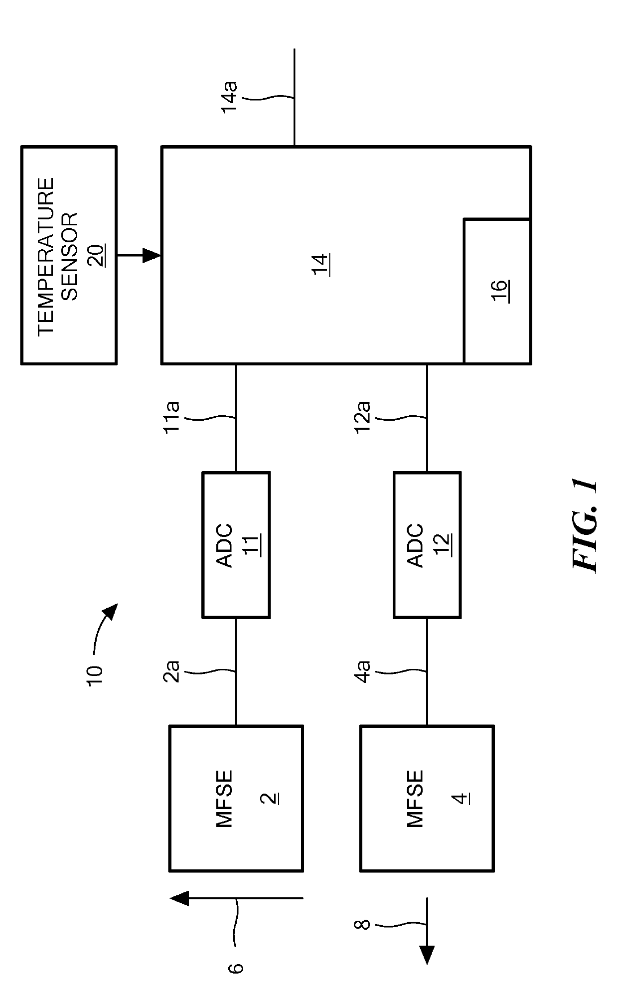
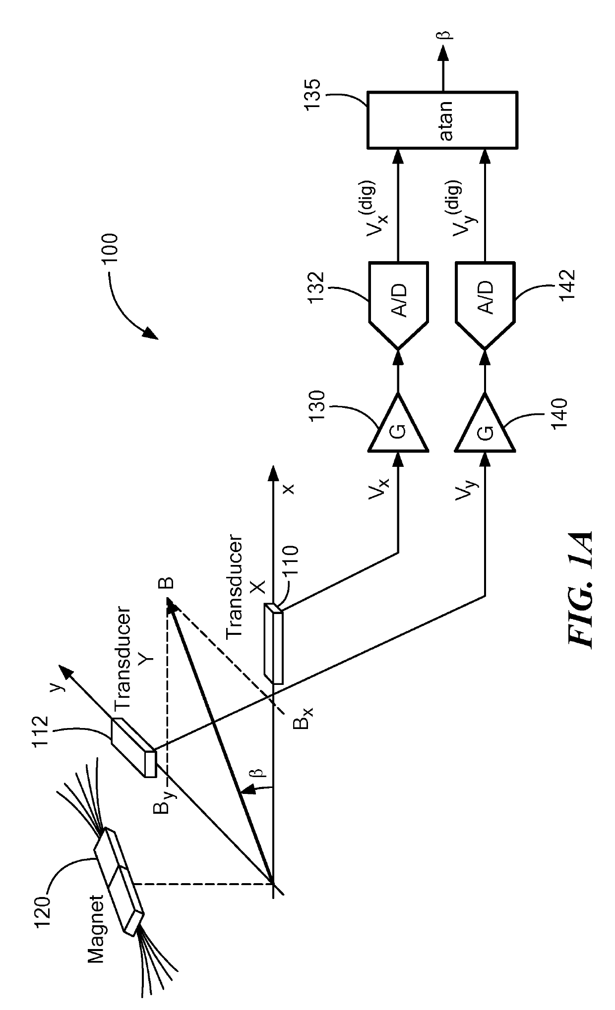
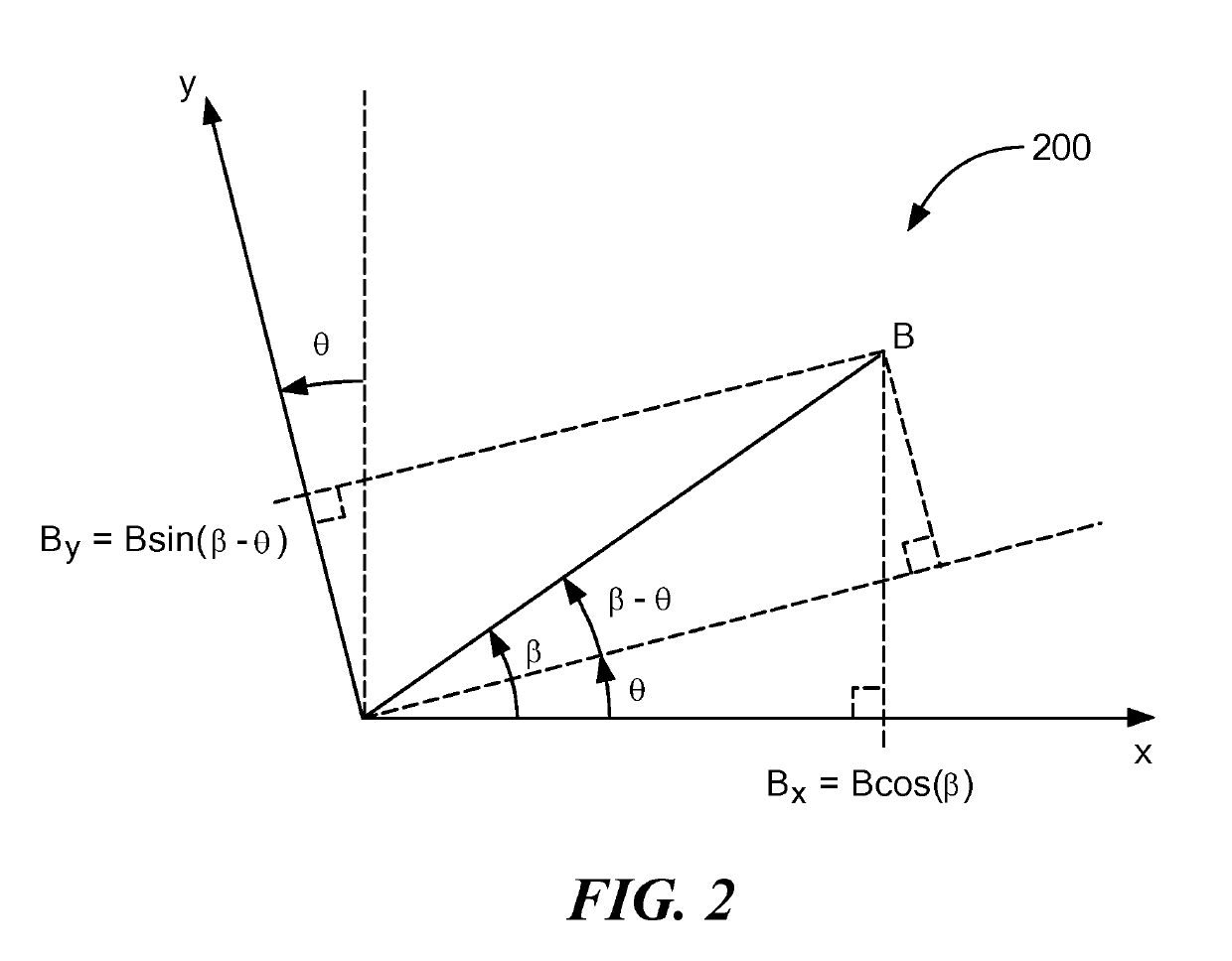
A magnetic field sensor includes a first magnetic field sensing element first generating a first signal having a first axis of maximum sensitivity, a second magnetic field sensing element for generating a second signal and having a second axis of maximum sensitivity, one or more detectors for receiving an output of the first magnetic field sensing element or the second magnetic field sensing element, and a processor that receives an output of the one or more detectors and uses the output of the one or more detectors to calculate a first constant Kc and a second constant Ks and then uses Kc and Ks to compensate for an orthogonality error between the first axis of maximum sensitivity and second axis of maximum sensitivity. The detectors include peak detectors and / or zero-crossing detectors that compare the output of the first input signal or the second input signal with a threshold or zero.

Description

CROSS REFERENCE TO RELATED APPLICATIONS[0001]This application is a Continuation-in-Part application of and claims the benefit under 35 U.S.C. § 120 of U.S. application Ser. No. 15 / 180,199 filed on Jun. 13, 2016, which is incorporated herein by reference in its entirety.STATEMENT REGARDING FEDERALLY SPONSORED RESEARCH[0002]Not Applicable.FIELD[0003]The present disclosure relates generally to addressing orthogonality error associated with a magnetic field angle sensor.BACKGROUND[0004]As is known, sensors are used to perform various functions in a variety of applications. Some sensors include one or magnetic field sensing elements, such as a Hall effect element or a magnetoresistive element, to sense a magnetic field associated with proximity or motion of a target object, such as a ferromagnetic object in the form of a gear or ring magnet, or to sense a current, as examples.[0005]Sensor integrated circuits are widely used in automobile control systems and other safety critical applicat...

Claims


Application Information

Patent Timeline
Patent Type & Authority Applications(United States)
IPC IPC(8): G01R35/00G01R33/02
CPCG01R35/00G01R33/02G01R33/0017G01R33/0029
Inventor RIGONI, NICOLASALPAGO, OCTAVIO H.BIBERIDIS, NICOLAS RAFAELROMERO, HERNAN D.
Owner ALLEGRO MICROSYSTEMS INC
Learn More