Boring tool

Active Publication Date: 2019-04-25
SANDVIK INTELLECTUAL PROPERTY AB
View PDF22 Cites 2 Cited by
  • Summary
  • Abstract
  • Description
  • Claims
  • Application Information

AI Technical Summary

Benefits of technology

[0019]According to an embodiment of the invention the motor member is configured to cause movement of the slider member by rotating a threaded member in engagement with a thread of the slider member, of a member arranged to move with the slider member or of a member fixed with respect to the tool body. Such a design of members for obtaining a transmission of movement from the motor member to the slider member will result in a high accuracy by simple means.
[0020]According to an embodiment of the invention the slider member is hollow and the motor member is arranged inside the slider member, which results in a very compact combinat

Problems solved by technology

An adjustability of said boring radius by more than 60% would result in a need of complicated transmissions and/or

Method used


Image

  • Boring tool
  • Boring tool
  • Boring tool

Examples


Embodiment Construction

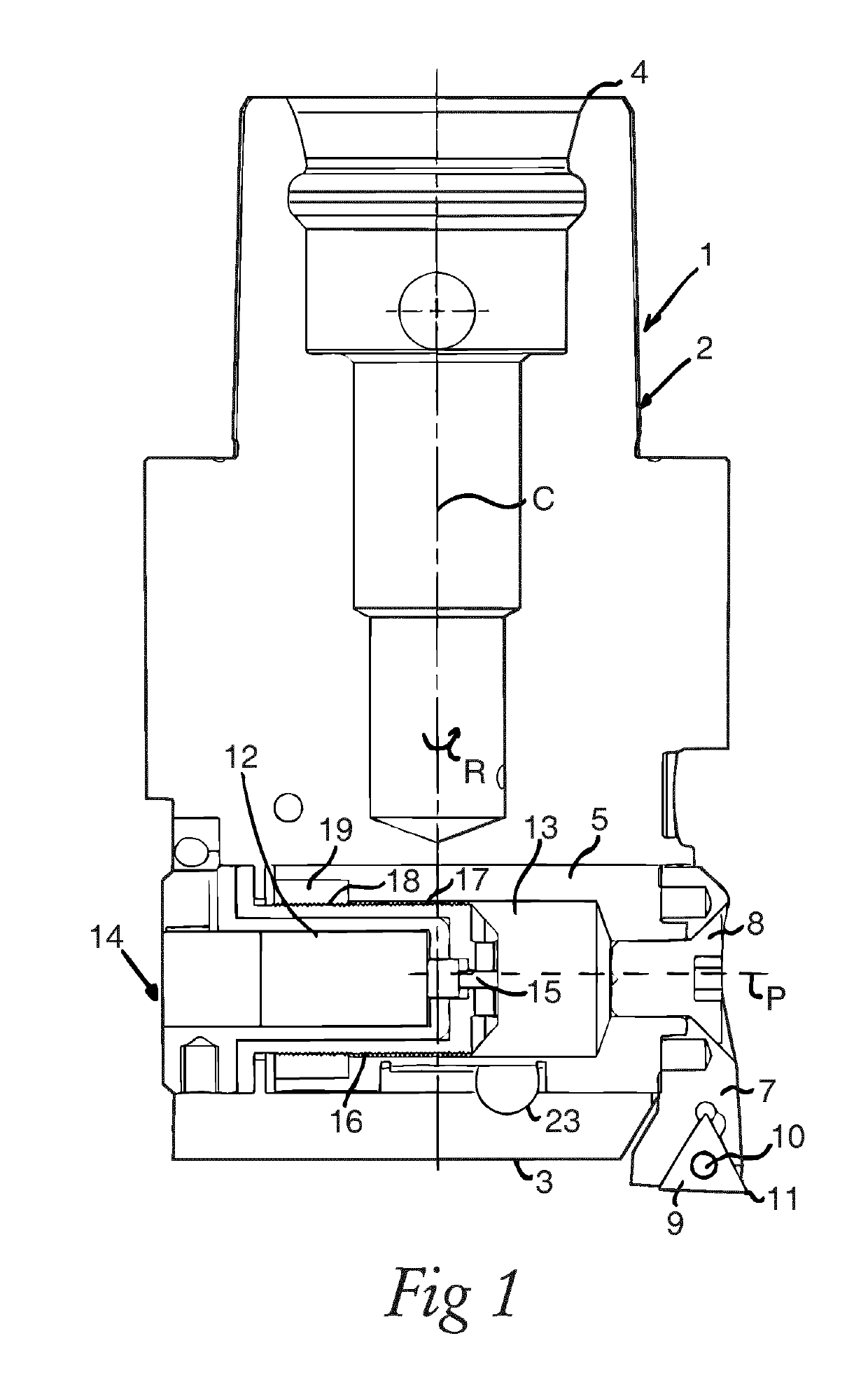
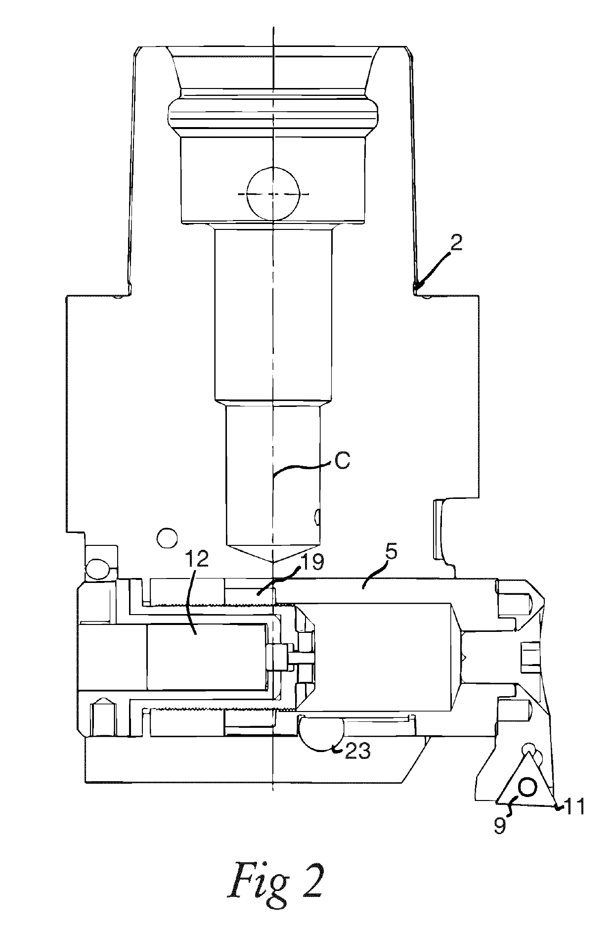
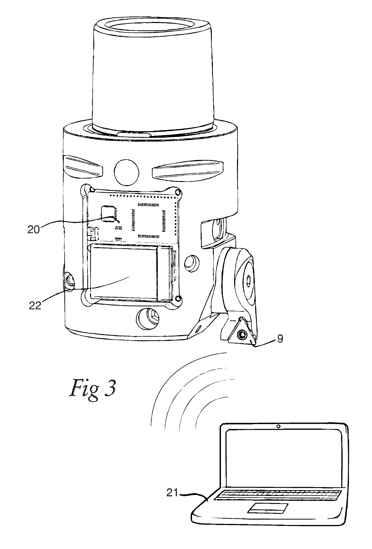
[0032]A boring tool 1 according to a first embodiment of the invention is shown in FIG. 1-3 and reference is made in parallel to these figures when now describing the design of the boring tool. The boring tool has a tool body 2 including a front end 3 and a rear end 4, between which a central rotation axis C extends around which the tool body is rotatable in a direction of rotation R. A slider member 5 is arranged movably inside the tool body along a path P (see dashed line in FIG. 1) extending transversely to the rotation axis C while being directed perpendicularly thereto. An insert pocket 6 (see FIG. 3) is associated with the slider member to move therewith by being arranged on a part 7 secured to the slider member 5 by a screw 8. The insert pocket is configured to receive a cutting insert 9 to be secured therein by a fastening member 10. The cutting insert has a cutting edge 11 and projects from the tool body transversely to the rotation axis C thereof so as to carry out a borin...


PUM


Abstract

A boring tool includes a tool body rotatable around a central rotation axis. A slider member is arranged movably inside the tool body along a path extending transversely to the rotation axis. An insert pocket is associated with the slider member to move therewith and configured to receive a cutting insert with a cutting edge and which projects from the tool body transversely to the rotation axis. A motor member is connected to the slider member and controllable to move the slider member transversely to the rotation axis for changing the distance of the cutting edge to the rotation axis. The motor member is arranged inside the tool body together with the slider member in a cutting part of the tool body at a front end thereof. The motor member is arranged in parallel with the transversal extension of the slider member along said path.

Description

TECHNICAL FIELD OF THE INVENTION[0001]The present invention relates to a boring tool comprising[0002]a tool body including a front end and a rear end, between which a central rotation axis extends around which the tool body is rotatable in a direction of rotation,[0003]a slider member which is arranged movably inside the tool body along a path extending transversely to said rotation axis,[0004]an insert pocket associated with the slider member to move therewith and configured to receive a cutting insert to be secured therein by a fastening member, which cutting insert has a cutting edge and projects from the tool body transversely to said rotation axis,[0005]a motor member connected to the slider member and controllable to move the slider member transversely to said rotation axis for changing the distance of the cutting edge of the cutting insert to said rotation axis and by that the radius to be created in a hole of a workpiece when bored by rotation of the tool body, and[0006]a co...

Claims


Application Information

Patent Timeline
IPC IPC(8): B23B29/034
CPCB23B29/03439B23B2260/062B23B2229/16
Inventor KARLSSON, ROBIN
Owner SANDVIK INTELLECTUAL PROPERTY AB
Why Eureka
Try Eureka