
Pneumatic Tire

Pending Publication Date: 2019-04-25
YOKOHAMA RUBBER CO LTD
View PDF1 Cites 3 Cited by
  • Summary
  • Abstract
  • Description
  • Claims
  • Application Information

AI Technical Summary

Benefits of technology

The present technology provide a pneumatic tire that can improve its performance on snow and ice and reduce noise in a compatible manner. This is achieved by designing the tire to have certain features that enhance its performance on snow and ice while also reducing noise.

Problems solved by technology

These grooves in the tread surface, however, cause noise when a vehicle runs.
However, when narrow grooves and the like are provided in the blocks, compressed air flows into the narrow grooves when the blocks contact the ground, readily flowing to main grooves and readily producing noise.
Thus, satisfaction of both performance on snow and ice and reduced noise has been extremely difficult.

Method used


Image

  • Pneumatic Tire
  • Pneumatic Tire
  • Pneumatic Tire

Examples


examples

[0066]FIGS. 6A to 6F are tables listing the results of performance tests of pneumatic tires. In relation to the pneumatic tire 1 described above, performance evaluation tests conducted on a pneumatic tire of a conventional example and the pneumatic tires 1 according to embodiments of the present technology will be described below. The performance evaluations tests were conducted on performance on snow and ice, which is traction performance when driving on icy and snowy road surfaces, pass-by noise which is noise produced as the pneumatic tire 1 rolls, and cracks or block breakage from the narrow groove 30 indicating failure of the block 20.

[0067]The performance evaluation tests were conducted by mounting the pneumatic tire 1 having a size of 315 / 70R22.5 defined by ETRTO on a regular rim, adjusting the air pressure to 900 kPa, mounting the tire onto a 2-D test vehicle, and then running tests. Each test item for performance on snow and ice was evaluated by having panelists run the tes...


PUM


Abstract

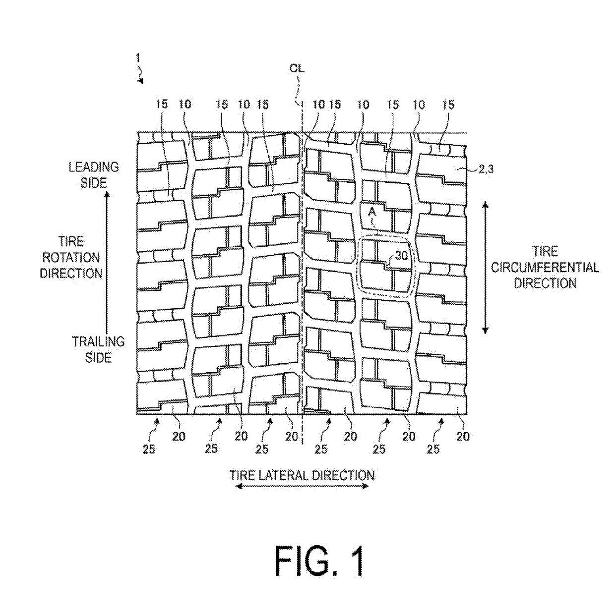
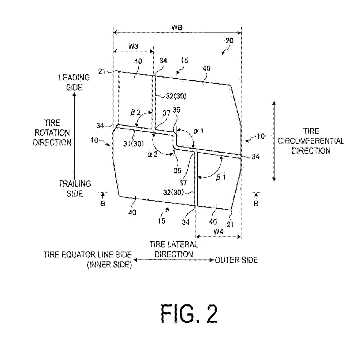
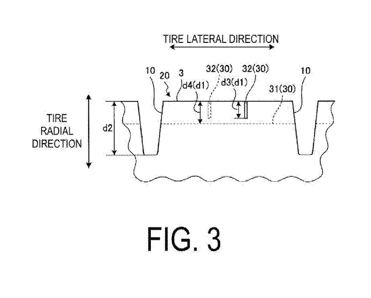
A pneumatic tire includes a tread surface, a plurality of circumferential main grooves formed on the tread surface and extending in a tire circumference direction, a plurality of lug grooves formed on the tread surface and extending in a tire lateral direction, a plurality of blocks defined by the lug grooves on both sides in the tire circumferential direction and by the circumferential main grooves on at least one end in the tire lateral direction, and narrow grooves formed in the blocks. The narrow grooves include a plurality of bent portions as well as a circumferential narrow groove extending in the tire circumference direction and a lateral narrow groove extending in the tire lateral direction. The lateral narrow groove and the circumferential narrow groove are configured so that at least one thereof is provided in a plurality and includes a plurality of intersection points where the one intersects the other.

Description

TECHNICAL FIELD[0001]The present technology relates to a pneumatic tire.BACKGROUND ART[0002]In a pneumatic tire, in order to discharge water between a tread surface and a road surface during running on wet road surfaces, a plurality of grooves are formed in the tread surface. These grooves in the tread surface, however, cause noise when a vehicle runs. Thus, among the pneumatic tires in the related art, there are tires that achieve reduced noise as a result of considerations made to a shape and an arrangement of the grooves. For example, in the pneumatic tire described in Japan Patent No. 5530059, outer longitudinal grooves positioned at or near both ends in a tire lateral direction are formed into zigzag shapes, and positions where the outer longitudinal grooves connect to lateral grooves, which are positioned on both sides of the outer longitudinal grooves in the tire lateral direction and connected to the outer longitudinal grooves from both sides of the outer longitudinal groove...

Claims


Application Information

Patent Timeline
IPC IPC(8): B60C11/03B60C11/12B60C11/13
CPCB60C11/0302B60C11/0306B60C11/1204B60C11/1236B60C11/1259B60C11/13B60C2011/1213B60C2011/1245B60C2011/0346B60C2011/0369B60C2200/06B60C2011/036B60C2011/0362B60C2011/0348B60C11/11B60C2011/0351B60C11/12B60C11/03B60C2011/1268
Inventor SUZUKI, TAKAYUKI
Owner YOKOHAMA RUBBER CO LTD
Learn More