Vehicle door glass run and method for assembling the same

a technology for vehicle doors and glass runs, applied in vehicle components, vehicle sealing arrangements, engine seals, etc., can solve the problems of increasing the friction force generated by the structure, affecting the safety of the vehicle, and the accidental detachment so as to reduce the sliding resistance of the trim strip, increase the anchoring strength of the glass run, and increase the anchoring strength of the trim strip

Active Publication Date: 2019-04-25
NISHIKAWA RUBBER
View PDF3 Cites 5 Cited by
  • Summary
  • Abstract
  • Description
  • Claims
  • Application Information

AI Technical Summary

Benefits of technology

[0034]The fifth aspect of the present disclosure allows for increasing the anchoring strength of the glass run body to the glass run mount.
[0035]The sixth aspect of the present disclosure allows for increasing the anchoring strength of the trim strip to the glass run body.
[0036]The seventh aspect of the present disclosure can sufficiently reduce the sliding resistance to the trim strip, further facilitating manual assembly of the trim strip on the glass run body by a worker.
[0037]The eighth aspect of the present disclosure can further reduce a force needed for assembly of the trim strip on the glass run body.
[0038]The ninth aspect of the present disclosure facilitates manual assembly of the trim strip on the glass run body by a worker without using any machine for trim strip assembly.
[0039]According to the tenth aspect of the present disclosure, the trim strip is preliminarily curvedly shaped, and the glass run body is preliminarily linearly shaped, reducing the sliding resistance. This can reduce a force needed for assembly of the trim strip on the glass run body.

Problems solved by technology

However, the trim strip may be accidentally detached from the glass run body after being assembled.
Thus, this structure increases a friction force generated between the trim strip and the contacting portion in sliding the trim strip in the assembly process.
Assembling the trim strip therefore requires a large force, which makes manual assembly of the trim strip by a worker more difficult.
This method, however, creates a gap between the glass run body and the upper part of the trim strip, resulting in deterioration of appearance.
Such a machine is less versatile and thus quite expensive.
In addition, fixing and installation of such a large machine are laborious, and introduction of the machine is therefore difficult.
This reduces the sliding resistance when the trim strip contacts the coating.
This reduces the sliding resistance when the trim strip slides on the coating.
This configuration sufficiently reduces the sliding resistance to the trim strip.

Method used


Image

  • Vehicle door glass run and method for assembling the same
  • Vehicle door glass run and method for assembling the same
  • Vehicle door glass run and method for assembling the same

Examples


first embodiment

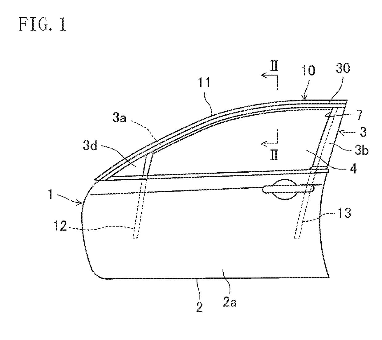
[0048]FIG. 1 is a side view of a left front door (a vehicle door) 1 having a left front door glass run (a vehicle door glass run) 10 according to a first embodiment of the present disclosure, viewed from the exterior (left side) of a vehicle cabin (hereinafter referred to as “the cabin”). The left front door 1 is installed to the left front side of a vehicle (not illustrated), and opens and closes an opening (not illustrated) formed in the left front side of the vehicle. A right front door (not illustrated) and the left front door are symmetrically equipped. The vehicle door glass run according to the present disclosure is mountable to the right and left rear doors (not illustrated).

[0049]In the description of this embodiment, the side closer to the front of the vehicle is simply referred to as “front,” and the side closer to the rear of the vehicle is simply referred to as “rear.” Further, a part of a component located in or closer to the cabin is simply referred to as “an interior...

second embodiment

[0099]FIGS. 5 and 6 relate to a second embodiment of the present disclosure. In the second embodiment, the configuration for assembly of the trim strip 30 is different from that of the first embodiment. In the following description, components that have been described in the first embodiment are designated by the same reference characters, and are not described in detail. The following description will focus on only differences from the first embodiment.

[0100]The trim strip 30 in the second embodiment has a larger vertical dimension H1 than the trim strip 30 in the first embodiment. Such a larger vertical dimension H1 of the trim strip 30 requires a larger vertical dimension H2 between the upper body-side mating portion 23a and the lower body-side mating portion 23b. However, because these portions are formed of a high-stiffness material, the larger vertical dimension H2 between the upper body-side mating portion 23a and the lower body-side mating portion 23b makes it difficult to d...

third embodiment

[0106]FIG. 7 relates to a third embodiment of the present disclosure. In the third embodiment, the configuration for assembly of the trim strip 30 is different from that of the first embodiment. In the following description, components that have been described in the first embodiment are designated by the same reference characters, and are not described in detail. The following description will focus on only differences from the first embodiment.

[0107]For the same reason as the second embodiment, the trim strip 30 in the third embodiment has an upper resin member 35 and a lower resin member 36 extending in the front-rear direction. A body of the trim strip 30 has, at its upper part, an upper bending portion 30a bending toward the interior of the cabin, and further has, at its lower part, a lower bending portion 30b bending toward the interior of the cabin.

[0108]The upper resin member 35 is designed to be fitted into the upper bending portion 30a of the body of the trim strip 30. The...


PUM


Abstract

A trim strip has upper and lower trim-strip-side mating portions. A glass run body has, at its exterior part, body-side mating portions and an upper contacting portion contacting an upper part of an exterior surface of the trim strip. The upper contacting portion has a portion contacting the trim strip, and the portion is provided with a coating. The coating is formed of an elastic material reducing the sliding resistance to the trim strip.

Description

CROSS-REFERENCE TO RELATED APPLICATION[0001]This application claims priority to Japanese Patent Application No. 2017-206105 filed on Oct. 25, 2017, the entire invention of which is incorporated by reference herein.BACKGROUND ART[0002]The present disclosure relates to a glass run mounted on a window frame of a vehicle door and a method for assembling the glass run.[0003]There are various types of vehicle side doors, one of which has a window frame holding a peripheral portion of a window glass. A door having such a window frame is provided with a glass run for sealing a gap between the window frame and the window glass (see, e.g., German Patent Application Publication No. 102014202802).[0004]The glass run described in German Patent Application Publication No. 102014202802 is assembled on a window frame from the exterior of a vehicle cabin. Such a glass run configured to be assembled on the window frame from the exterior of the cabin, as described in German Patent Application No. 1020...

Claims


Application Information

Patent Timeline
Patent Type & Authority Applications(United States)
IPC IPC(8): B60R13/04B60J10/33B60J10/265B60J10/76B60J10/16
CPCB60R13/04B60J10/33B60J10/265B60J10/76B60J10/16B60J10/88
Inventor TOMOYASU, SHINGOMIYATA, TOMONORI
Owner NISHIKAWA RUBBER
Why Eureka
Try Eureka