Anchor rod

A technology of anchor rod and screw rod, which is applied in the direction of construction, sheet pile wall, foundation structure engineering, etc., can solve the problem of low anchor strength and achieve the effect of improving anchor strength

Pending Publication Date: 2019-06-07
罗定市麟千机电有限公司
View PDF0 Cites 5 Cited by
  • Summary
  • Abstract
  • Description
  • Claims
  • Application Information

AI Technical Summary

Problems solved by technology

[0004] The purpose of the present invention is to provide a kind of anchor rod, to alleviate the technical problem that the anchoring strength of the anchor rod in the wall is low in the prior art

Method used


Image

  • Anchor rod
  • Anchor rod
  • Anchor rod

Examples


Embodiment

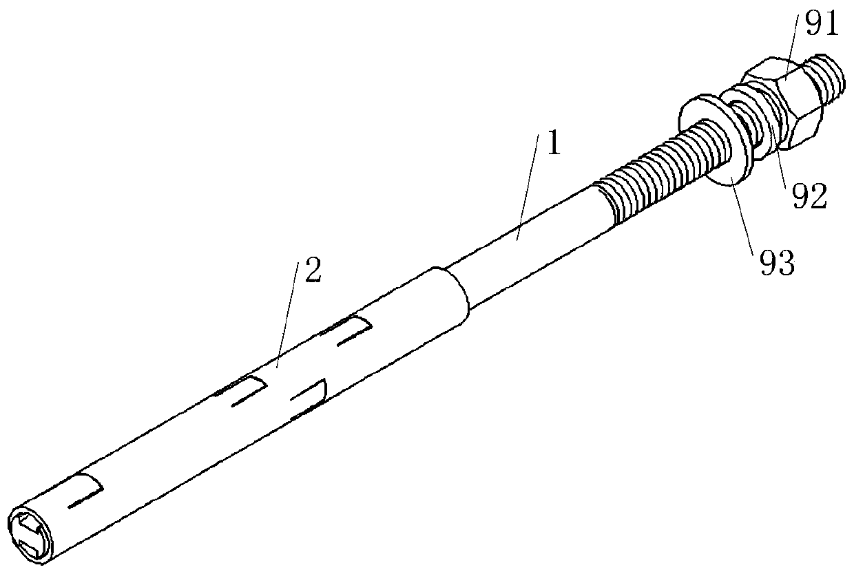
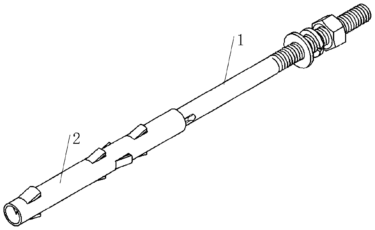
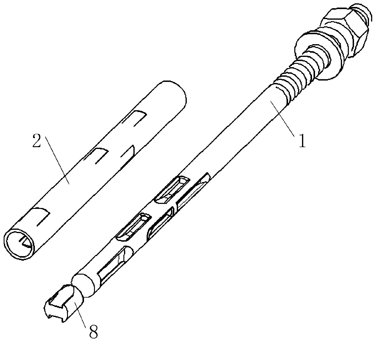
[0041] see Figure 1-Figure 9 As shown, this embodiment provides an anchor rod, which includes a screw rod 1 and a casing 2; a first limiting hole 21 is opened on the peripheral wall of the casing 2, and a first blade is connected in the first limiting hole 21 3, and the first blade 3 protrudes from the inner peripheral surface of the sleeve 2, the screw 1 is inserted into the sleeve 2, and when the screw 1 moves inside the sleeve 2 along its axis direction, the screw 1 can push the first blade 3 It protrudes from the outer peripheral surface of the sleeve 2 through the first limiting hole 21 . That is, in this embodiment, the thickness of the first vane 3 along the radial direction of the sleeve 2 is greater than the diameter of the sleeve 2 .

[0042] When the anchor is in use, the sleeve 2 and the screw 1 are inserted together into the anchor hole on the wall, wherein, during the movement of the screw 1 in the sleeve 2 along its axis direction, the screw 1 and the first st...


PUM


Abstract

The invention relates to the technical field of hardware tools, in particular to an anchor rod. The anchor rod comprises a screw rod and a sleeve; a first limiting hole is formed in the circumferential wall of the sleeve, a first blade is connected into the first limiting hole, and the first blade protrudes out of the inner circumferential surface of the sleeve; the screw rod is arranged in the sleeve in an inserted mode, when the screw rod moves in the sleeve in the axis direction, the screw rod can push the first blade to protrude from the outer circumferential surface of the sleeve throughthe first limiting hole. The anchor rod solves the technical problem that an anchor rod existing in the prior art has lower anchorage strength in a wall body.

Description

technical field [0001] The invention relates to the technical field of hardware tools, in particular to an anchor rod. Background technique [0002] Anchor rods are widely used in various engineering constructions (especially traffic engineering), mainly by pouring grouting body (concrete) around the anchor rod and between the walls, so that the anchor rod and the wall are bonded into a whole to provide anchor The rod provides anchoring force. However, the anchoring force between the anchor rod and the wall is mainly determined by the cohesive force of the slurry material, and the source of the anchoring force is single, resulting in a relatively limited pull-out force on the anchor rod. In the engineering of pulling force, the quality problem that the anchor rod and the grouting body fall off from the anchor hole at the same time often occurs, which seriously threatens the safety of the project and affects the construction progress. [0003] Therefore, the present applica...

Claims


Application Information

Patent Timeline
Patent Type & Authority Applications(China)
IPC IPC(8): E02D5/74
Inventor 陈平武
Owner 罗定市麟千机电有限公司
Why Eureka
Try Eureka