Anchoring type connecting device for steel bar wedge cone and connecting method thereof

A technology of connecting device and wedge cone, which is applied to structural elements, building components, building reinforcements, etc., can solve the problems of increased trouble, poor economy, and large area of ​​force contact, and achieves convenient operation process and high quality assurance rate. , the effect of small force area

Active Publication Date: 2015-02-04
NINGBO CONSTR ENG GROUP
View PDF5 Cites 5 Cited by
  • Summary
  • Abstract
  • Description
  • Claims
  • Application Information

AI Technical Summary

Problems solved by technology

Sleeve extrusion refers to putting the connecting ends of the two steel bars that need to be butted into the same sleeve, and then extruding the sleeve with external force, so that the sleeve and the steel bars are squeezed tightly. The peripheral surface is extruded into the outer peripheral surface of the steel bar, the contact area is large, and the extrusion force to be provided is also large, so it is necessary to use special strong extrusion machinery and equipment, and it is operated by a special person, so it is very inconvenient
Although the threaded connection does not need to use a special powerful extrusion machine, it must be operated by a special person to tap the external thread at the end of the steel bar that needs to be connected.
Although the amount of steel connection is large, it is relatively scattered in terms of time, so the utilization rate of processing machinery at the construction site is low, and the economy is poor
However, if the end of the steel bar is processed in batches, it will bring a series of problems such as material procurement, protection, storage, and transportation of the end of the steel bar after processing, which will increase various unnecessary troubles

Method used


Image

  • Anchoring type connecting device for steel bar wedge cone and connecting method thereof
  • Anchoring type connecting device for steel bar wedge cone and connecting method thereof
  • Anchoring type connecting device for steel bar wedge cone and connecting method thereof

Examples


Embodiment Construction

[0033] The present invention will be further described below in conjunction with the drawings and specific embodiments.

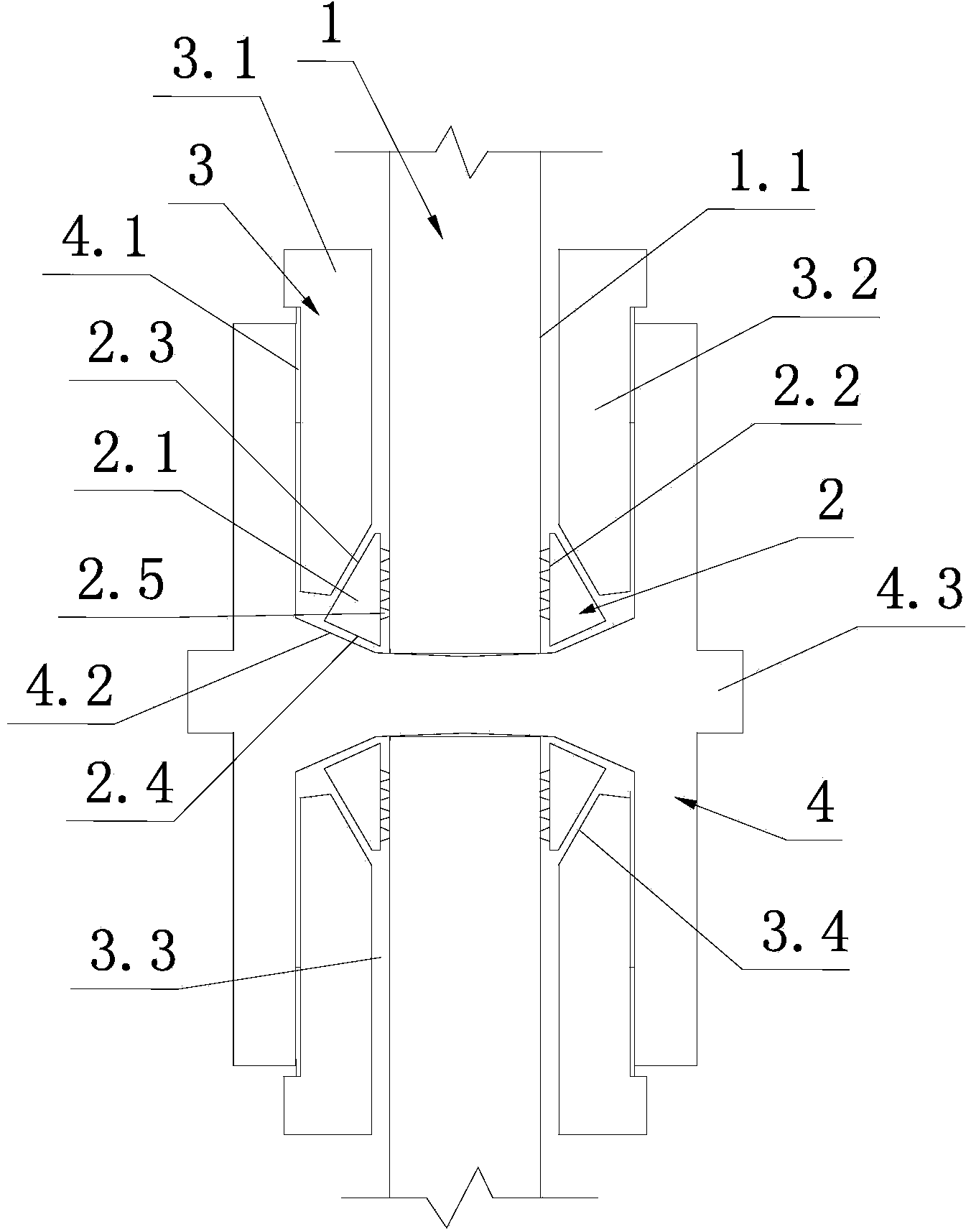
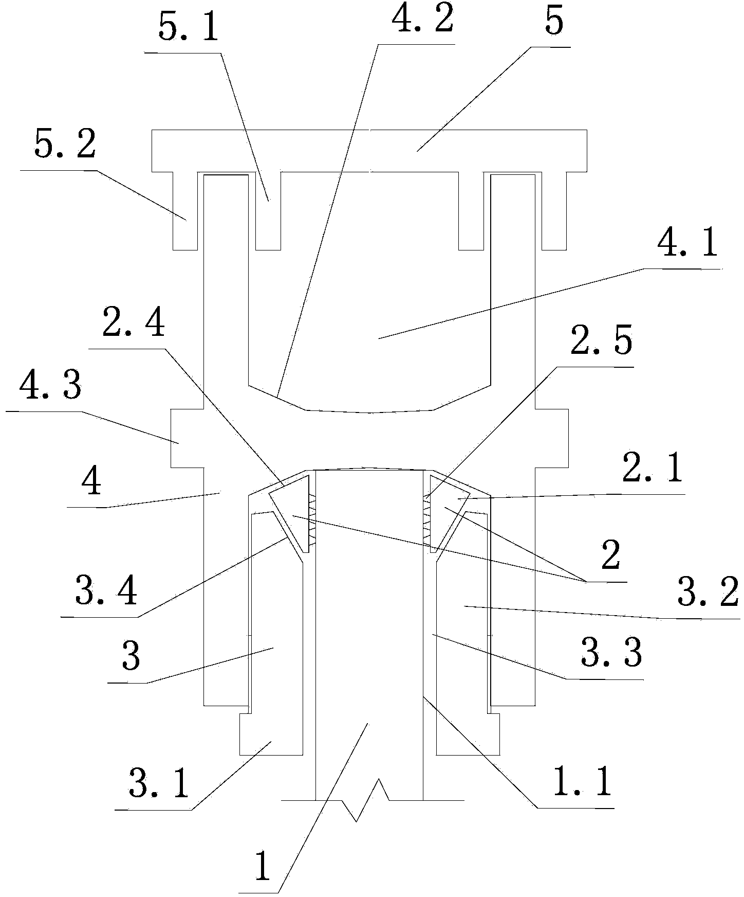
[0034] Such as figure 1 , figure 2 , image 3 , Figure 4 , Figure 5 As shown, the steel wedge-cone anchoring connecting device of the present invention includes the connected steel bar 1, the wedge-taper sleeve 2, the inner sleeve special-shaped nut 3, the outer sleeve support frame 4 and the sealing plate 5.

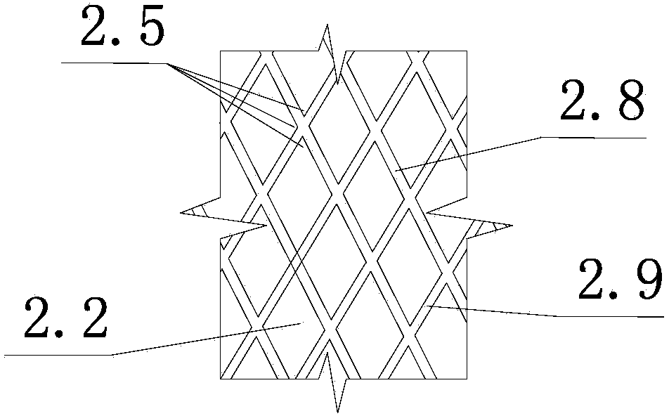
[0035] The inner cylinder wall of the wedge cone sleeve 2 is a first cylindrical surface 2.2, the outer cylinder wall is a first conical surface 2.3, the bottom surface of the cylindrical cone is a second conical surface 2.4, the top surface of the small cone is a circular ring plane, and the first cylindrical surface 2.2 Serrated teeth 2.5 are provided, and each wedge cone sleeve 2 is formed by buckling two symmetrical semi-circular arc clips 2.1. Each semi-circular arc clip 2.1 is provided with a horizontal ring groove 2.6 for accommodating the iron...


PUM


Abstract

The invention discloses an anchoring type connecting device for a steel bar wedge cone and a connecting method thereof. The anchoring type connecting device comprises a connected steel bar (1), a wedge cone sleeve (2), an inner sleeve specially-shaped nut (3) and an outer sleeve support frame (4), wherein the connected steel bar (1) is supported by the sawteeth (2.5) of the wedge cone sleeve (2); the second conical surface (2.4) of the wedge cone sleeve (2) supports against a blind hole (4.1) of the outer sleeve support frame (4); the wedge cone sleeve (2) is supported by the inner sleeve specially-shaped nut (3); and the inner sleeve specially-shaped nut (3) is screwed with the outer sleeve support frame (4). The connecting method is characterized in that the external thread of the inner sleeve specially-shaped nut (3) is screwed into the internal thread of the blind hole (4.1) of the outer sleeve support frame (4). The connecting device and the connecting method which are disclosed by the invention have the advantages of easiness and convenience in operation, no need of adopting special machining equipment, firmness in connecting effect and ideal tensile strength of connected steel bars, and residual deformation amount accords with a design standard after connection.

Description

Technical field [0001] The invention relates to a reinforcing steel connecting device and technology, in particular to a reinforcing steel wedge-cone anchoring connecting device and a connecting method. Background technique [0002] In the construction of steel bars of cast-in-place concrete structures, due to factors such as raw materials and production technology, steel bars are usually delivered in straight strips with a length of 12m to 15m. Therefore, the connection of steel bars is inevitable. At present, the connection methods of steel bars mainly include welding connection and mechanical connection. [0003] The advantage of welding connection is that the connection structure is compact, the transmission force is clear, and there is basically no increase in auxiliary parts, but the power consumption is large and the operation is complicated. The construction operation is affected by environmental factors such as wind and light. Even if it cannot work in rainy days, it will...

Claims


Application Information

Patent Timeline
Patent Type & Authority Applications(China)
IPC IPC(8): E04C5/18
Inventor 吴佳雄徐文卫钱久军何建明刘用海朱宗裕
Owner NINGBO CONSTR ENG GROUP
Why Eureka
Try Eureka