Systems and methods of additive printing of functional electronic circuits

a functional electronic circuit and additive manufacturing technology, applied in the field of additive systems, can solve the problems of affecting the electrical and mechanical properties of materials formed by the additive manufacturing process, affecting the young's modulus of materials, and limited 3d printing processes for electronic devices

Active Publication Date: 2019-04-25
MORNINGBIRD MEDIA CORP
View PDF0 Cites 3 Cited by
  • Summary
  • Abstract
  • Description
  • Claims
  • Application Information

AI Technical Summary

Benefits of technology

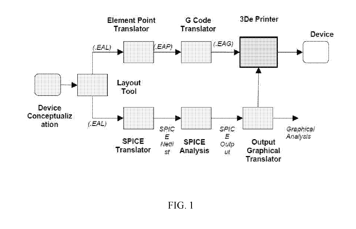
[0014]Exemplary embodiments of the present disclosure relate to systems and methods for creating electronic devices with steps that can be purely additive, eliminating the need for the masking and removal steps of the known circuit creation techniques. This can be accomplished via a three dimensional printer that can utilize various conductive and non-conductive materials to print the desired circuit onto a base layer such that no excess is laid down on the base, which would require masking and removal.

Problems solved by technology

Known 3D printing processes for electronic devices are limited to planar only printing with possible adjustments in a third dimension (2.5 Dimensional printing).
Post processing techniques such as oven heating or laser treatment can adversely affect the electrical and mechanical properties of materials that have been formed by the additive manufacturing process.
For example, post processing techniques using extreme heat can alter Young's modulus of the material.
This can significantly impact the desired performance of an electrical or electronic circuit.
However, the materials printed using the known polymer binding agents can be brittle, and therefore unsuitable for 3D printing of electronic devices.
Currently, there are no semiconductor ink materials that are available, which allow for direct 3D printing of semiconductor devices and hence there are no 3D printers which have such ink materials.
Technology challenges in overcoming the above noted issues include (1) preparation of ink-based printing materials necessary for realizing the desired electrical properties for the 3D electronic devices; (2) deposition and process of the ink-based materials for 3D electronics, and (3) the complexity of computer aided design software control to produce a functional 3D electronic device.

Method used


Image

  • Systems and methods of additive printing of functional electronic circuits
  • Systems and methods of additive printing of functional electronic circuits
  • Systems and methods of additive printing of functional electronic circuits

Examples


second embodiment

Using UV Curable Liquid Epoxy

[0061]Liquid epoxy can affect the conductivity of the semiconductor ink, and may vary in various aspects of the present disclosure. The UV curing intensity and curing time can also affect the electrical properties of a semiconductor ink-based composition, and may vary in various aspects of the present disclosure.

[0062]An exemplary embodiment of the present disclosure is directed to a process of manufacturing an electronic device using ultraviolet (UV) curable liquid epoxy. The process can involve mixing UV curable liquid epoxy with at least one nanopowder to form a mixture, dispensing the mixture on a non-conducting glass surface, curing the dispensed mixture using an UV light emitting diode (LED) source, and melting the cured mixture to a semi-liquid state that is extruded from a print head to form the device. The LED source can have a maximum intensity of about 16 MW / cm2 and duration for the curing can be between about 20 seconds and about 120 seconds....


PUM

PropertyMeasurementUnit
particle sizeaaaaaaaaaa
temperatureaaaaaaaaaa

Abstract

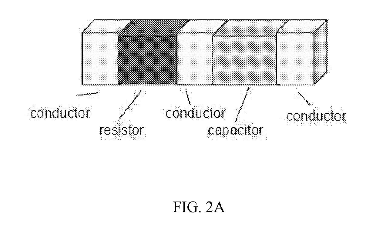
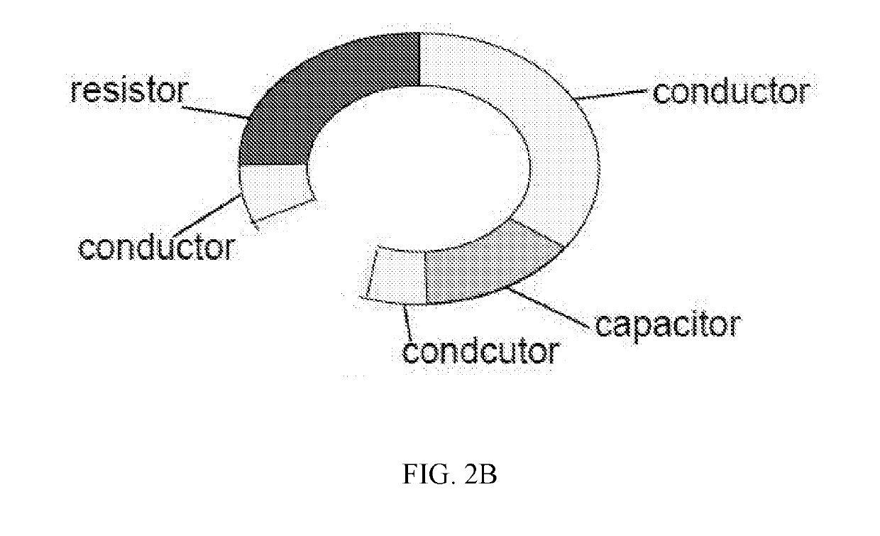
A composition, method, and system for directly printing and creating complete functional 3D electronic circuits and devices without any thermal or laser post-processing treatment, by using at least Triphenylamine (TPA) as a powder binding agent. The composition can have mechanical characteristics that allow it to be melted and extruded on a structure, and electrical properties that allow it to function as at least one of a conductor, insulator, resistor, p-type semiconductor, n-type semiconductor, or capacitor.

Description

CROSS-REFERENCE TO RELATED APPLICATIONS[0001]This application claims priority to U.S. Provisional Application No. 62 / 559,795 filed on Sep. 18, 2017, the entire content of which is incorporated herein by reference.STATEMENT REGARDING FEDERALLY SPONSORED RESEARCH OR DEVELOPMENT[0002]This invention was made with government support under contract NNX16CM40P awarded by the National Air & Space Administration (NASA). The government may have certain rights in the invention.FIELD[0003]The present disclosure relates to additive systems and methods of creating functional electronic circuits and circuit boards.BACKGROUND INFORMATION[0004]3D printing is any of various processes in which a material is joined or solidified under computer control to create a three-dimensional object, with the material being added together (such as liquid molecules or powder grains being fused together). 3D printing can be used in both rapid prototyping and additive manufacturing. Objects typically are produced usi...

Claims


Application Information

Patent Timeline
Patent Type & Authority Applications(United States)
IPC IPC(8): C09D11/104C09D11/02C09D11/101C09D11/102C09D11/037C09D11/52H01B3/42H01B1/24H01C17/065H01G4/33H01L21/02H05K3/12H01G4/12B29C64/118B29C64/291B29B11/10B33Y10/00B33Y70/00
CPCC09D11/104C09D11/02C09D11/101C09D11/102C09D11/037C09D11/52H01B3/421H01B1/24H01C17/0652H01G4/33H01L21/02532H01L21/02422H05K3/1283H01G4/1218H01L21/02664H01C17/06586H01L21/02623B29C64/118B29C64/291B29B11/10B33Y10/00B33Y70/00B29K2063/00B29K2105/162B29K2505/14B29K2067/046C09D11/322H01L21/02628H01L21/02527H01L21/02601
Inventor GLENN, CHANCE M.
Owner MORNINGBIRD MEDIA CORP
Why Eureka
Try Eureka