Eureka AIR delivers breakthrough ideas for toughest innovation challenges, trusted by R&D personnel around the world.

Deployable Fan with Linear Actuator

a technology of linear actuator and deployable fan, which is applied in the direction of non-positive displacement fluid engine, pump components, liquid fuel engine components, etc., can solve the problems of corrosion of the slip ring contacts, high cost of slip ring, and inability to meet the expected life of the ceiling fan, etc., to achieve low cost, low energy consumption, and durable

Active Publication Date: 2019-04-25
SWISS MODULE GROUP
View PDF11 Cites 8 Cited by
  • Summary
  • Abstract
  • Description
  • Claims
  • Application Information

AI Technical Summary

Benefits of technology

The patent describes a solution for blading a fan that is low-cost, durable, and uses less energy than similar products. It can be easily controlled and adjusted over the lifespan of the product, and is easy to operate with existing remote controls. The solution also produces excellent sound quality, is compact in size and can be used with a variety of housing designs.

Problems solved by technology

This approach is lacking because slip rings tend to be expensive and wear out too quickly for the expected life of a ceiling fan.
There is also a problem with coordinating the deployment of the blades, and with corrosion of the slip ring contacts during typical long periods when the fan is not used.
This approach has proven to work, but is difficult to implement into a commercial product.
The required clutches are noisy, prone to wear, and difficult to control accurately.
Coordinating the main motor speed in all conditions in order to ensure smooth blade action has been a challenge with this design.
In short, this approach has not given the quality experience customers would expect from a high-end ceiling fan.

Method used


Image

  • Deployable Fan with Linear Actuator
  • Deployable Fan with Linear Actuator
  • Deployable Fan with Linear Actuator

Examples


Embodiment Construction

[0029]The detailed description set forth below in connection with the appended drawings is intended as a description of presently-preferred embodiments of the invention and is not intended to represent the only forms in which the present invention may be constructed or utilized. The description sets forth the functions and the sequence of steps for constructing and operating the invention in connection with the illustrated embodiments. It is to be understood, however, that the same or equivalent functions and sequences may be accomplished by different embodiments that are also intended to be encompassed within the spirit and scope of the invention.

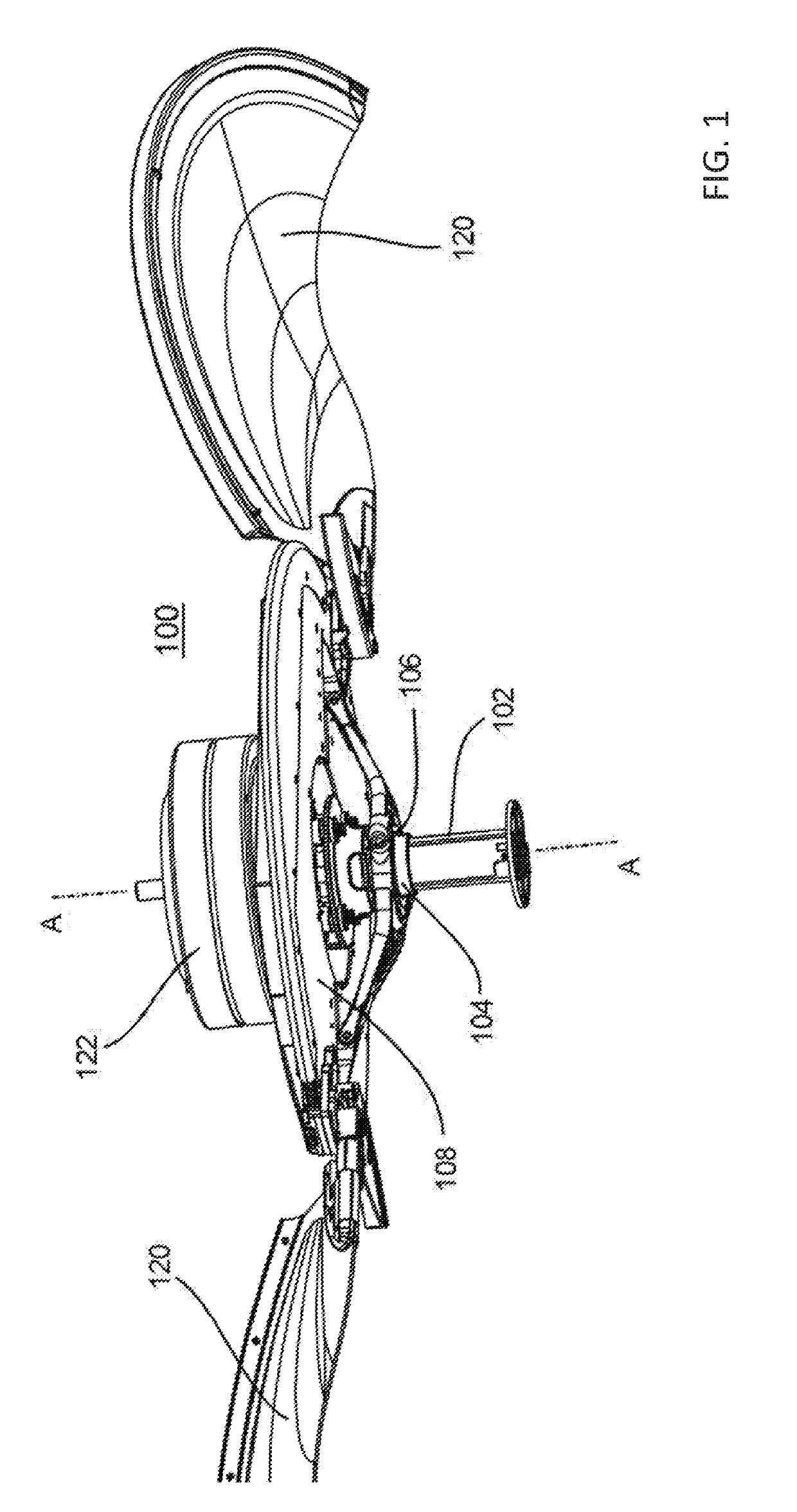
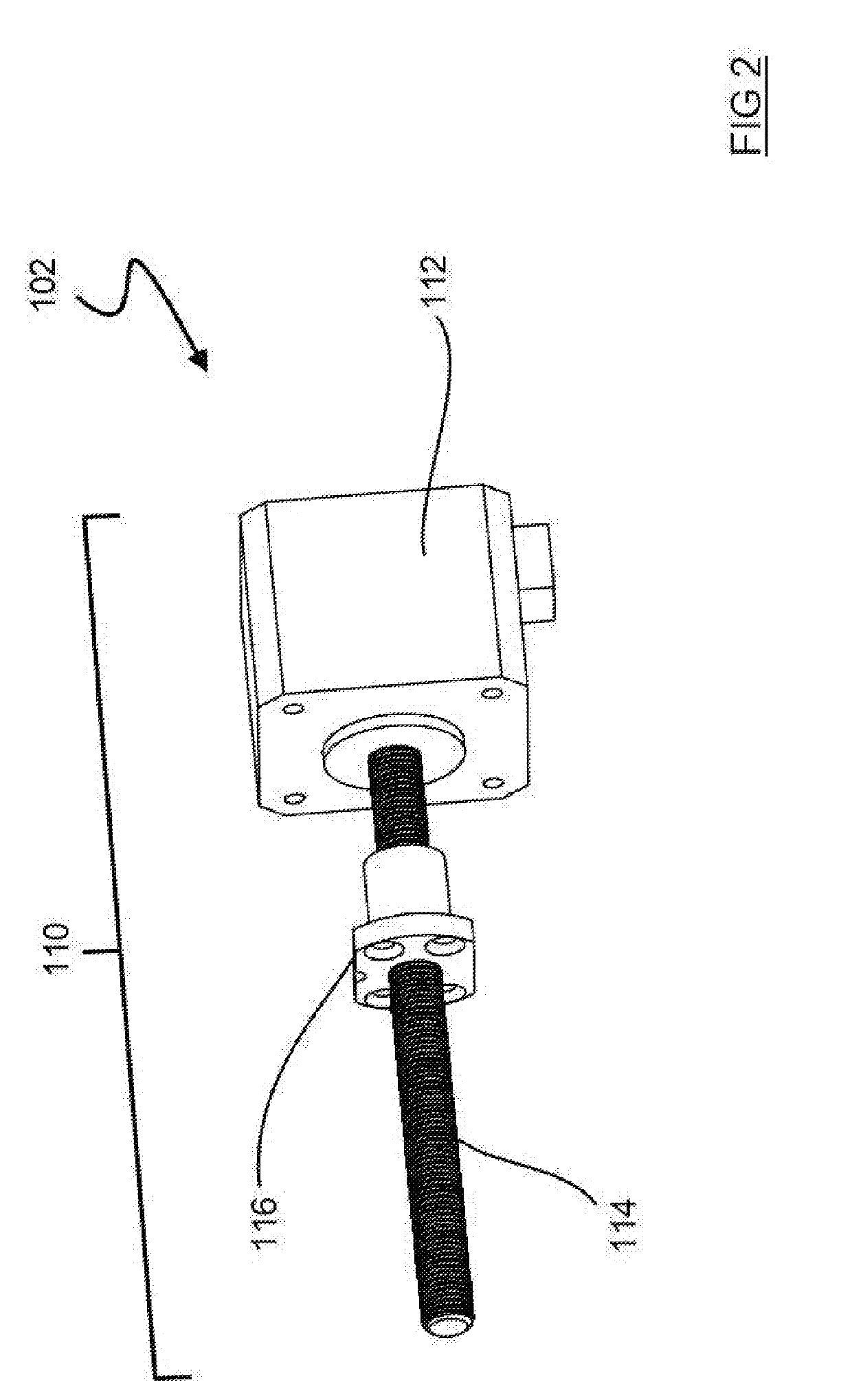
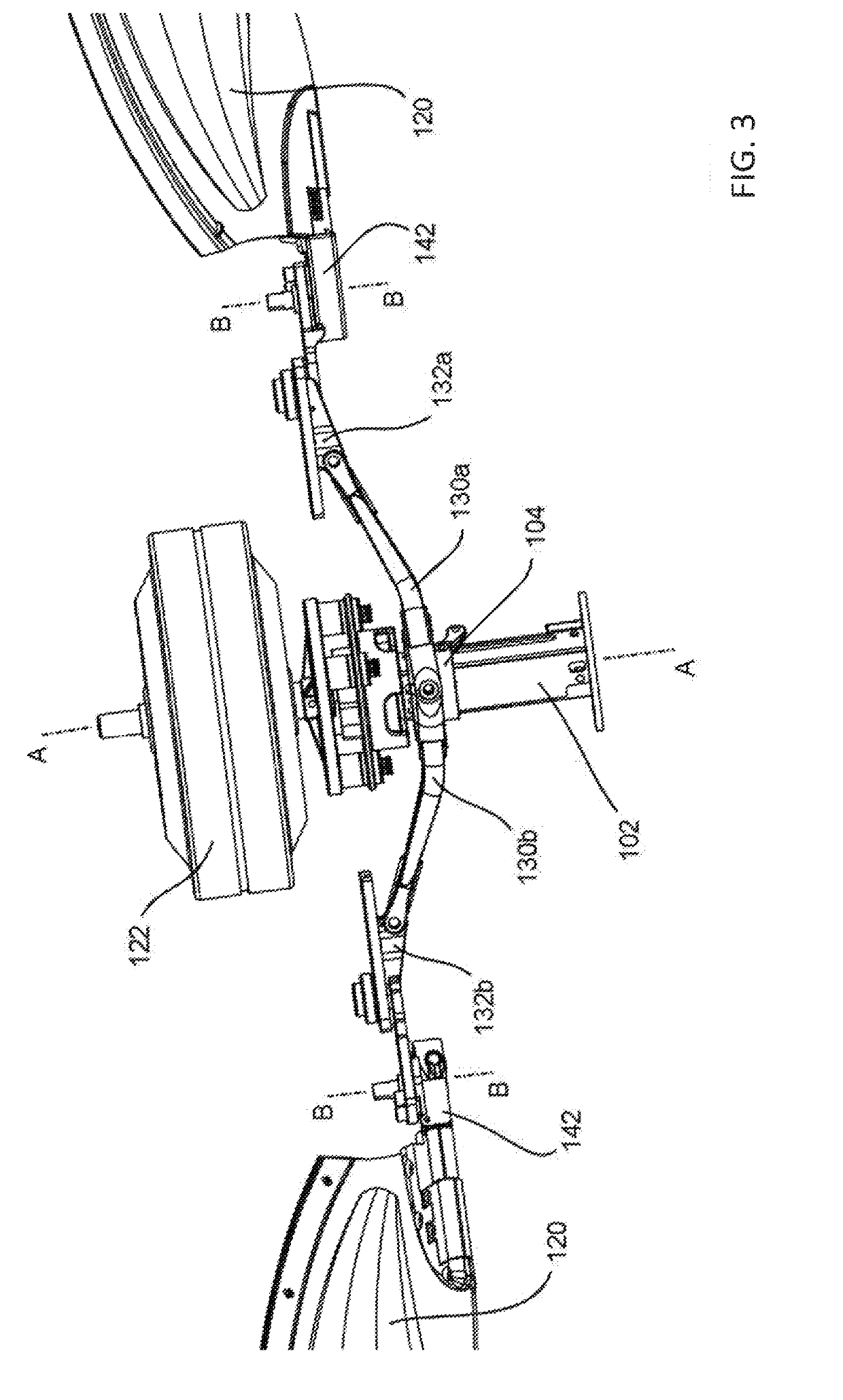
[0030]The invention of the present application is a system and method of automatically deploying and stowing one or more fan blades 120 by moving a carriage 104 in a first linear direction along a linear actuator 102 mounted to a fan motor 122, wherein the carriage 104 is operatively connected to the fan blade to rotate with the fan blade ...


PUM


Abstract

A linear actuator for use with a fan with deployable fan blades to deploy the fan blades when in use and stow the fan blades when not in use. The linear actuator utilizes a drive element having a driver that moves linearly along a shaft of the linear actuator. Linear movement of the driver causes radial movement of arms connected to the linear actuator and the fan blades. Radial movement of the arms causes rotational movement of gears attached to the ends of the fan blades to cause the fan blades to rotate into the deployed or stowed configuration.

Description

CROSS-REFERENCE TO RELATED APPLICATION[0001]This patent application claims the benefit of U.S. Provisional Patent Application Ser. No. 62 / 575,890, entitled “Deployable Fan with Linear Actuator,” filed Oct. 23, 2017, which application is incorporated in its entirety here by this reference.BACKGROUND[0002]The basic powered blade deployment of a ceiling fan is covered by U.S. Pat. No. 7,857,591 B2, which is incorporated in its entirety here by this reference. The individual fan blades are mounted to a rotating platform that is powered by a main fan motor. Development of the technology for commercial use has depended upon a good solution for transmitting controllable power to this rotating platform, for precisely actuating the fan blades.[0003]Initial designs used one or more electric motors on the rotating platform to actuate the blades. This relied on a rotating electrical interface, or slip ring. This approach is lacking because slip rings tend to be expensive and wear out too quickl...

Claims


Application Information

Patent Timeline
IPC IPC(8): F04D29/36F04D25/08
CPCF04D29/364F04D25/088
Inventor CONLEY, WILLIAM P.THOMASON, RODGER D.LOPEZ, RICARDO GARIVALDO
Owner SWISS MODULE GROUP
Why Eureka
Eureka Blog
Learn More