Optical fiber sensor and optical fiber sensor system

a technology of optical fiber and optical fiber, applied in the direction of instruments, electromagnetic transmission, transmission, etc., can solve the problems of difficult identification of position and difficulty in accurately acquiring position, and achieve the effect of less susceptible to nois

Active Publication Date: 2019-04-25
NEC CORP
View PDF4 Cites 5 Cited by
  • Summary
  • Abstract
  • Description
  • Claims
  • Application Information

AI Technical Summary

Benefits of technology

[0035]It is possible for an optical fiber sensor and an optical fiber sensor system according to the present disclosure to propagate two lights in mutually opposite directions through a single optical fiber while making it less susceptible to noise.

Problems solved by technology

When the waveform indicating the polarization fluctuation detected in the first polarization fluctuation detector is different from that detected in the second polarization detector, it is difficult to accurately acquire the above timing difference, and thus the identification of the position becomes difficult.

Method used


Image

  • Optical fiber sensor and optical fiber sensor system
  • Optical fiber sensor and optical fiber sensor system
  • Optical fiber sensor and optical fiber sensor system

Examples


Embodiment Construction

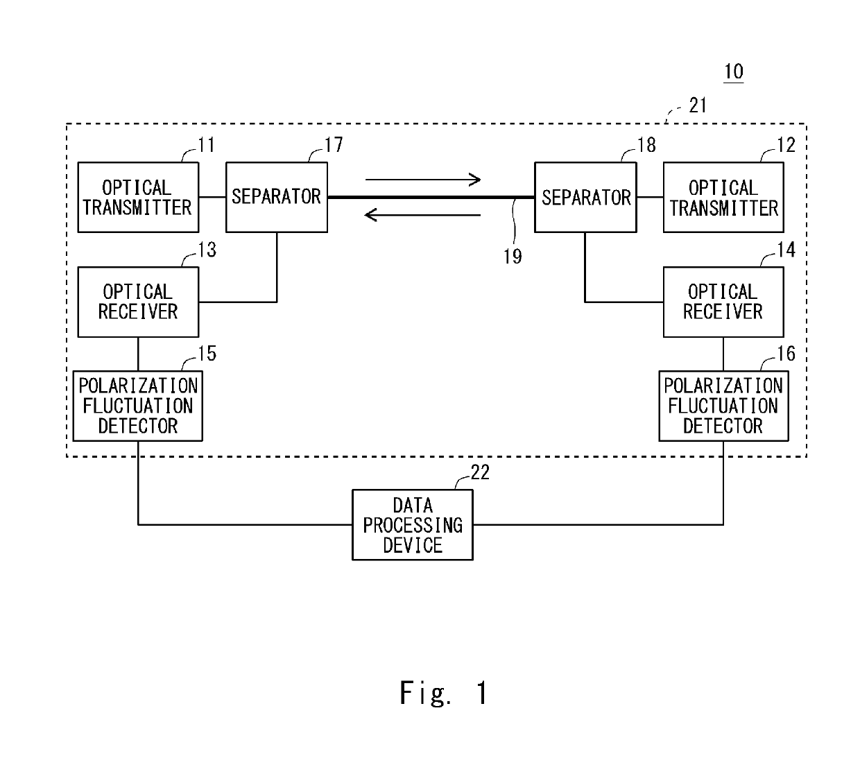
[0049]Prior to describing embodiments of the present disclosure, an overview of the present disclosure will be described. FIG. 1 shows an optical fiber sensor system according to the present disclosure. An optical fiber sensor system 10 includes am optical fiber sensor 21, a data processing device 22. The optical fiber sensor 21 includes optical transmitters 11 and 12, optical receivers 13 and 14, polarization fluctuation detectors 15 and 16, separators 17 and 18, and an optical fiber 19.

[0050]The optical fiber 19 is an optical fiber for propagating (guiding) a light, and an optical fiber which changes a polarization state of the propagating light when at least one of a vibration and a displacement occurs. In the optical fiber sensor 21, the optical transmitter 11, the optical receiver 13, the polarization fluctuation detector 15, and the separator 17 are arranged at one end of the optical fiber 19, and the optical transmitter 12, the optical receiver 14, the polarization fluctuatio...


PUM


Abstract

An optical fiber changes a polarization state of a propagating light when at least one of a vibration and a displacement occurs. An optical transmitter inputs a first wavelength light to the optical fiber via a separator, and an optical transmitter inputs a second wavelength light to the optical fiber via a separator. The first and second wavelength lights propagated through the optical fiber in mutually opposite directions are respectively received by optical receivers (13 and 12) via the separators (18 and 17), and a fluctuation of a polarization is detected in polarization fluctuation detectors (16 and 15). A data processing device collects data indicating the fluctuation of the polarization detected by the polarization fluctuation detector and data indicating the fluctuation of the polarization detected by the polarization fluctuation detector.

Description

TECHNICAL FIELD[0001]The present disclosure relates to an optical fiber sensor and an optical fiber sensor system, more particularly, to an optical fiber sensor which detects at least one of a vibration and a displacement using an optical fiber, and an optical fiber sensor system including an optical fiber sensor of that kind.BACKGROUND ART[0002]Before now, various sensors using an optical fiber have been proposed. For example, Patent Literature 1 discloses an intrusion position detection device using an optical fiber as a sensor. The intrusion position detection device disclosed in Patent Literature 1 includes a first optical fiber and a second optical fiber arranged adjacent to each other in an area to be monitored. The first optical fiber and the second optical fiber respectively cause a fluctuation of a polarization in a propagated light in response to an external force.[0003]In the intrusion position detection device disclosed in Patent literature 1, a light source is arranged ...

Claims


Application Information

Patent Timeline
Patent Type & Authority Applications(United States)
IPC IPC(8): G01D5/34G01D5/353H04B10/25
CPCG01D5/344G01D5/35383H04B10/2504H04B10/58H04B10/6162G01D5/35351H04B10/85G08G1/04G01B11/26G01B11/00H04B10/07H04B10/25891
Inventor SUZAKI, TETSUYUKI
Owner NEC CORP
Why Eureka
Try Eureka