
Vehicle control apparatus and vehicle control method

a technology of vehicle control and control apparatus, which is applied in the direction of pedestrian/occupant safety arrangement, scene recognition, instruments, etc., can solve the problems of high probability of improper acquisition of specific points, and unnecessary operation in various types

Active Publication Date: 2019-04-25
DENSO CORP
View PDF0 Cites 4 Cited by
  • Summary
  • Abstract
  • Description
  • Claims
  • Application Information

AI Technical Summary

Benefits of technology

The patent text describes a problem where errors in detecting the position of specific points on an object can cause unnecessary operation in controlling the vehicle's movement to improve safety. The solution provided is a vehicle control system that prevents such errors by changing the way collision avoidance control is performed based on the difference in movement directions between the specific points. This ensures that the vehicle does not perform unnecessary operations due to errors in the position of the object.

Problems solved by technology

In a case where the position of a specific point of an object is detected from an image captured by an imaging section, an error may occur in the acquired position of the specific point due to the shape and pattern of the outer surface of the object, its attachments, and the like.
The error in the position of the specific point causes a change in the movement track calculated on the basis of the position, and the change may result in unnecessary operation in various types of control for improving traveling safety of the vehicle.
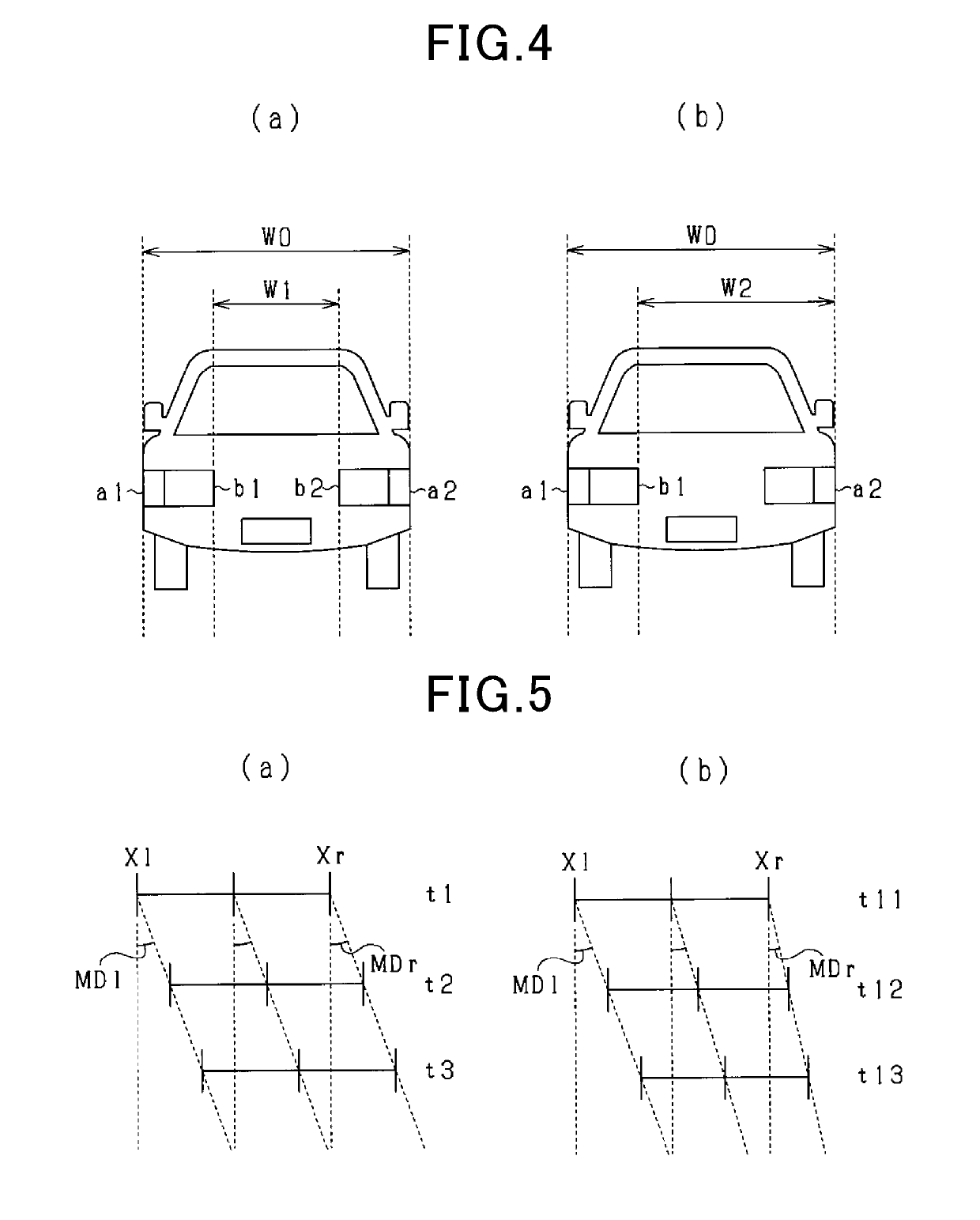
Therefore, if there is a difference between the movement directions of the respective specific points, the probability that the acquired specific points are improper is high.
If the acquired specific points are improper, collision avoidance control against the object is not properly performed, and unnecessary operation is liable to occur frequently.

Method used


Image

  • Vehicle control apparatus and vehicle control method
  • Vehicle control apparatus and vehicle control method
  • Vehicle control apparatus and vehicle control method

Examples


first embodiment

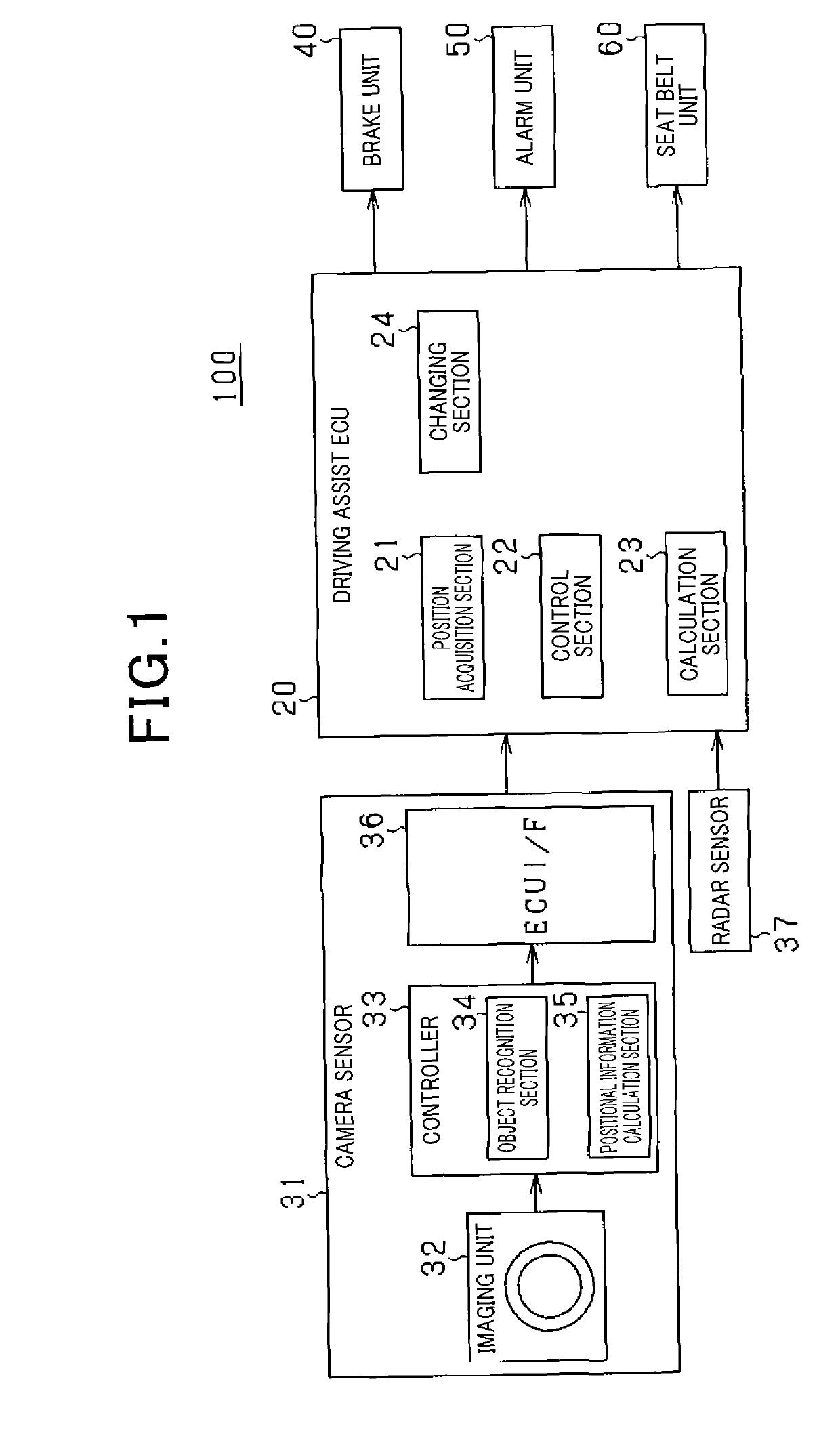
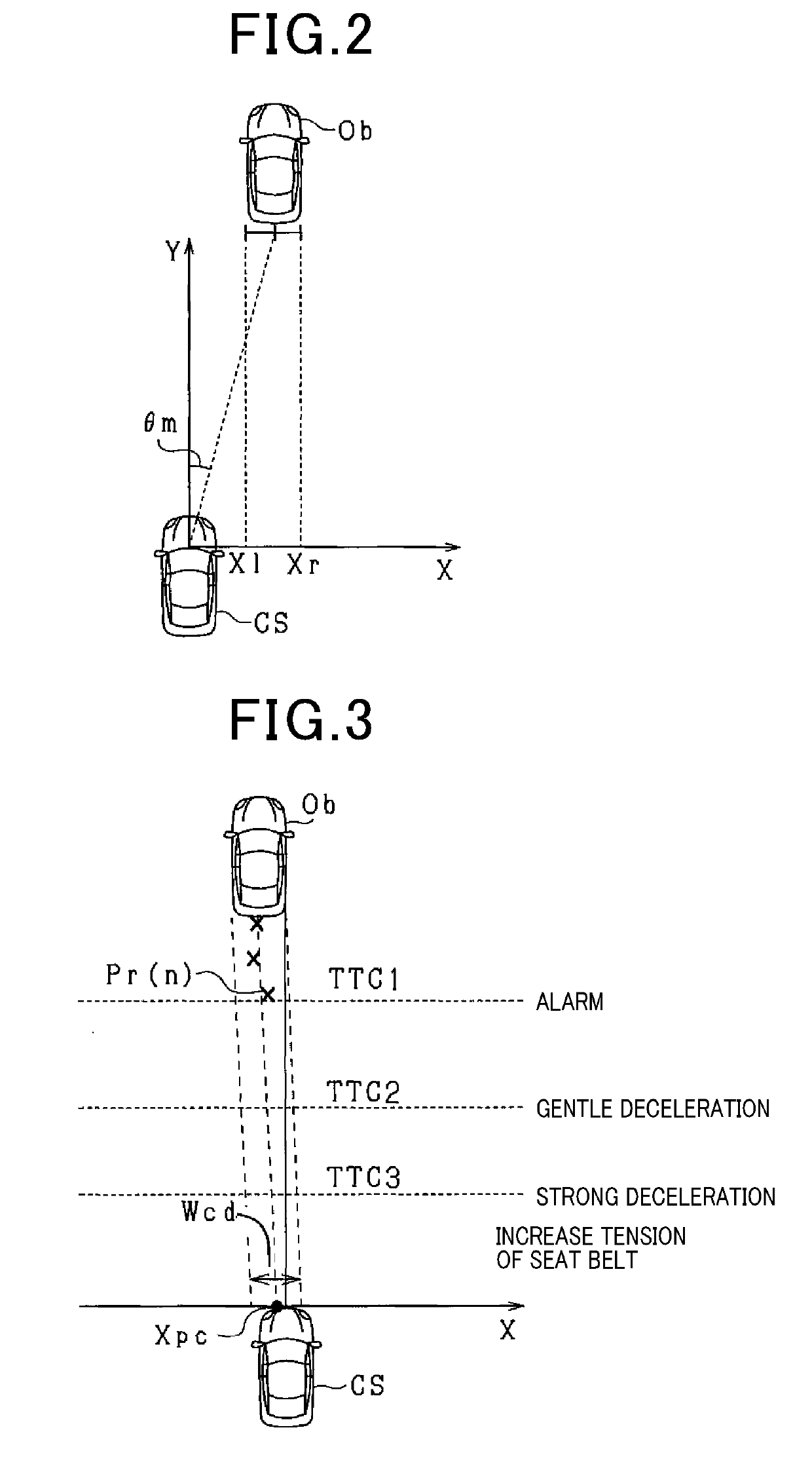
[0022]FIG. 1 illustrates a pre-crash safety system (hereinafter referred to as a PCSS) 100 to which a vehicle control apparatus and a vehicle control method are applied. The PCSS 100 is an example of a vehicle system installed in a vehicle, for example, and detects an object located ahead. In the event that the vehicle is in danger of colliding with the detected object, the PCSS 100 avoids or mitigates the collision between the vehicle and the object. Hereinafter, a vehicle equipped with the PCSS 100 is referred to as an own vehicle CS, and an object to be detected is referred to as a target Ob.

[0023]As illustrated in FIG. 1, the PCSS 100 includes various sensors, a driving assist ECU 20, a brake unit 40, an alarm unit 50, and a seat belt unit 60. In the embodiment illustrated in FIG. 1, the driving assist ECU 20 functions as a vehicle control apparatus.

[0024]Various sensors are connected to the driving assist ECU 20 to output the result of detecting the target Ob to the driving ass...

second embodiment

[0068]In the second embodiment, the driving assist ECU 20 changes how to perform PCS on the basis of the difference ΔMD in the movement direction and the relative speed Vr of the target Ob with reference to the own vehicle CS. As used herein, the relative speed Vr with reference to the own vehicle CS means a value obtained by subtracting the own vehicle speed Vs from the relative speed Vr of the target Ob. In the present embodiment, the direction in which the target Ob moves close to the own vehicle CS is a positive direction, and the direction in which the target Ob moves away from the own vehicle CS is a negative direction.

[0069]FIGS. 9(a) and 9(b) illustrate changes of lateral positions of targets Ob having different relative speeds Vr. The target Ob illustrated in FIG. 9(a) has a smaller relative speed Vr than that of the target Ob illustrated in FIG. 9(b).

[0070]The movement direction MD of a lateral position can also be expressed by a ratio between the relative speed Vy of the ...

third embodiment

[0076]In the third embodiment, in a case where the driving assist ECU 20 changes how to perform PCS, the driving assist ECU 20 makes the operation easy or difficult to activate using different degrees of change.

[0077]FIG. 10(a) illustrates an example of temporal changes of the difference ΔMD in the movement direction during periods T1 to T3. In FIG. 10(a), the difference ΔMD (|MDr−MDl|) in the movement direction temporarily becomes small during period T2 compared with those during periods T1 and T3. In this case, the reduction of the difference ΔMD in the movement direction during period T2 is accidental. Therefore, even though the determination region Wcd is reduced for making the operation of PCS easy to activate, the difference ΔMD in the movement direction increases again during period T3, and the determination region Wcd has to be expanded. In addition, expanding the determination region Wcd is not preferable because it is liable to facilitate unnecessary operation of PCS.

[0078...


PUM


Abstract

A driving assist ECU acquires, based on an image, positions of at least two specific points of an object that are different in a lateral direction with respect to a vehicle traveling direction. The driving assist ECU also performs collision avoidance control for avoiding a collision with the object based on a movement track of the object obtained from a history of the positions of the specific points, and calculates, for each of the specific points, a movement direction of each of the specific points based on the history of the position of each of the specific points. The driving assist ECU then changes how to perform the collision avoidance control based on a difference between the movement directions at the respective specific points.

Description

CROSS-REFERENCE TO RELATED APPLICATION[0001]The present application is based on Japanese Patent Application No. 2016-086409 filed on Apr. 22, 2016, the description of which is incorporated herein by reference.TECHNICAL FIELD[0002]The present disclosure relates to a vehicle control apparatus and a vehicle control method for detecting an object present ahead of a vehicle.BACKGROUND ART[0003]Conventionally, various types of control are proposed for detecting objects present around an own vehicle such as other vehicles and pedestrians by an imaging section and for improving traveling safety of the vehicle on the basis of the result of detecting the objects. For example, a vehicle control apparatus that actuates a brake unit and notifies the driver is proposed. Such a vehicle control apparatus calculates a movement track of a detected object on the basis of the position of the object, and performs various types of control for avoiding a collision between the own vehicle and the object on...

Claims


Application Information

Patent Timeline
IPC IPC(8): G08G1/16B60R21/00B60T7/12
CPCG08G1/16B60R21/00B60T7/12G08G1/166B60T7/22B60T2201/022B60W30/09B60W2720/106G01S13/931G01S2013/9325G01S13/867G01S17/86G01S17/931B60W2554/801G06V20/58B60W30/08B60K31/00
Inventor TAKAKI, RYO
Owner DENSO CORP
Learn More