Eureka AIR delivers breakthrough ideas for toughest innovation challenges, trusted by R&D personnel around the world.

Flattened DC brushless motor pump

Inactive Publication Date: 2019-04-25
HSU HSIA YUAN
View PDF3 Cites 0 Cited by
  • Summary
  • Abstract
  • Description
  • Claims
  • Application Information

AI Technical Summary

Benefits of technology

The present invention is a flattened DC brushless motor pump designed to be hidden in a working machine to save space. The motor pump has a flat design with a reduced length of the shaft, making it easy to install in machines. Overall, the invention achieves a slimmer and more compact motor pump that can be easily integrated into various machines.

Problems solved by technology

Therefore, the motor pump cannot be compact, which occupies the space of use.

Method used


Image

  • Flattened DC brushless motor pump
  • Flattened DC brushless motor pump
  • Flattened DC brushless motor pump

Examples


Embodiment Construction

[0021]Embodiments of the present invention will now be described, by way of example only, with reference to the accompanying drawings.

[0022]FIG. 6 is an exploded view in accordance with a first embodiment of the present invention. FIG. 7 is another exploded view in accordance with the first embodiment of the present invention. The present invention discloses a flattened DC brushless motor pump 100, which comprises a base 10, a silicon steel sheet unit 20, and an impeller 30.

[0023]The base 10 has a stator chamber 11 and a vortex chamber 12. The base 10 includes a base plate 13 between the stator chamber 11 and the vortex chamber 12. The base plate 13 has a first face 131 and a second face 132 corresponding to the stator chamber 11 and the vortex chamber 12 respectively. The first face 131 of the base plate 13 is provided with a hollow shaft housing 14. The shaft housing 14 is formed with a shaft chamber 15 at the second face 132 of the base plate 12. The shaft chamber 15 is in commun...


PUM


Abstract

A flattened DC brushless motor pump is provided. A first part of a silicon steel sheet unit is attached to a first face of a base plate and a second part of the silicon steel sheet unit is wound with a coil unit so that the coil unit does not overlap the height of a blade member of an impeller so as to reduce the length of a shaft of the impeller, such that the height of a base can be reduced to achieve the advantage of flattening. Thus, the flattened DC brushless motor pump can be hidden in a working machine to reduce the space of use.

Description

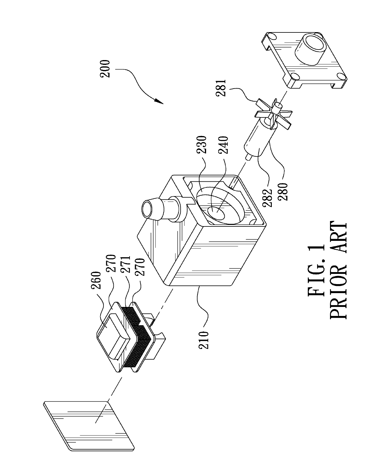
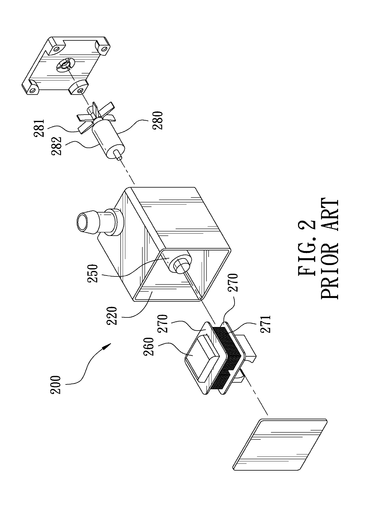
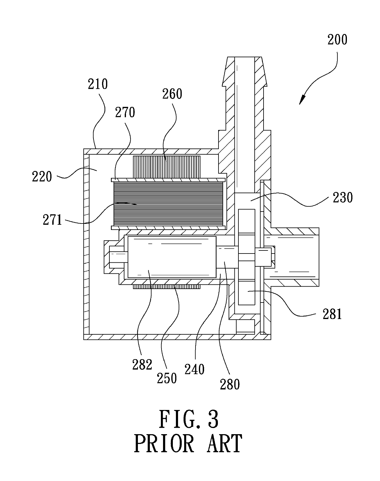
FIELD OF THE INVENTION[0001]The present invention relates to a motor pump, and more particularly, to a flattened DC brushless motor pump.BACKGROUND OF THE INVENTION[0002]FIG. 1 is an exploded view of a first conventional motor pump. FIG. 2 is another exploded view of the first conventional motor pump. FIG. 3 is a sectional view of the first conventional motor pump. The first conventional motor pump 200 has a main body 210. The main body 210 has a stator chamber 220, a vortex chamber 230, and a shaft chamber 240. The vortex chamber 230 is in communication with the shaft chamber 240. The shaft chamber 240 is provided with a shaft housing 250 in the stator chamber 220. The shaft housing 250 is engaged with a silicon steel sheet unit 260. The silicon steel sheet unit 260 is fitted with two insulating sheets 270. Two coil units 271 are wound between the two insulating sheets 270. The vortex chamber 230 and the shaft chamber 240 are provided with an impeller 280. Through the rotation of t...

Claims


Application Information

Patent Timeline
IPC IPC(8): H02K1/14H02K1/02H02K7/14F04D25/06F04D29/22
CPCH02K1/143H02K1/02H02K7/14F04D25/06F04D29/2238F04D13/0613F04D13/064F04D29/426
Inventor HSU, HSIA-YUAN
Owner HSU HSIA YUAN
Why Eureka
Eureka Blog
Learn More