
Vehicle front portion structure

Active Publication Date: 2019-05-02
TOYOTA JIDOSHA KK
View PDF0 Cites 5 Cited by
  • Summary
  • Abstract
  • Description
  • Claims
  • Application Information

AI Technical Summary

Benefits of technology

This patent describes a configuration that prevents the front side member from moving rearward in a vehicle accident, which could allow the collision load to escape to the rear. By using a projecting wall to regulate the movement of the bent front side member, the front side cross portion is designed to come into contact with a protruding portion to effectively restrain deformation. This results in a more reliable transmission of the collision load to the MC cross member.

Problems solved by technology

During a small overlap collision or an oblique collision, the collision load that is input from a collision body may not be sufficiently received by the front side member.
In addition, the rotary electric machine unit is a high-voltage part in the first place, and thus collision load transmission to the front side member on the opposite side via the rotary electric machine unit is undesirable.

Method used


Image

  • Vehicle front portion structure
  • Vehicle front portion structure
  • Vehicle front portion structure

Examples


Embodiment Construction

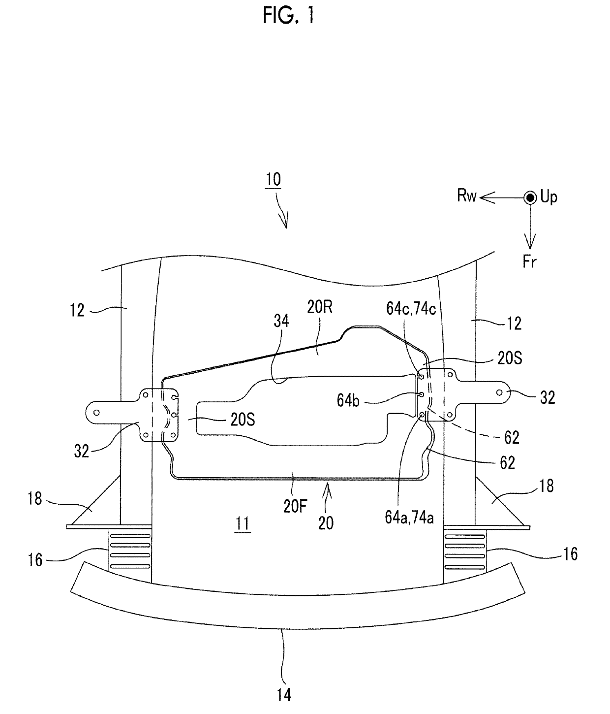
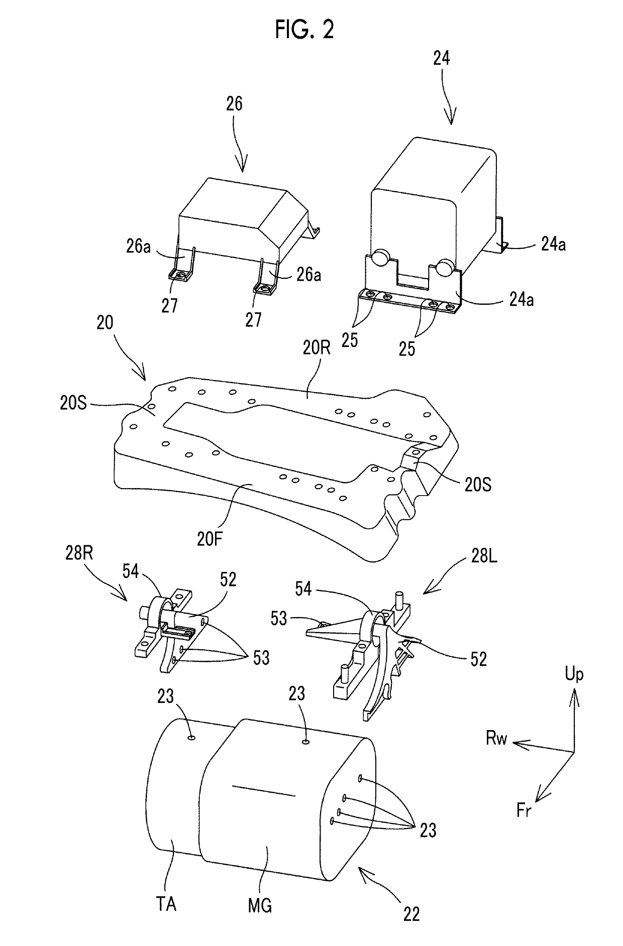
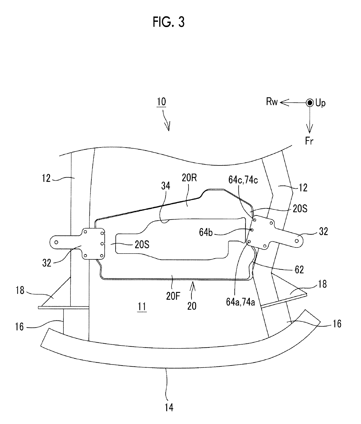
[0049]Hereinafter, a vehicle front portion structure 10 will be described with reference to accompanying drawings. FIG. 1 is a schematic plan view of the vehicle front portion structure 10. FIG. 2 is an exploded perspective view of a motor compartment cross member (hereinafter, referred to as an “MC cross member 20”) and the vicinity thereof. In the drawings, the axis that is indicated by a symbol Fr represents the front-rear direction of a vehicle, the axis that is indicated by a symbol Rw represents the width direction of the vehicle, and the axis that is indicated by a symbol Up represents the height direction of the vehicle. Unless otherwise noted, the right and left in the following description means the right and left from the point of view of an occupant of the vehicle.

[0050]An overall configuration of the vehicle front portion structure 10 will be briefly described first. The vehicle front portion structure 10 is incorporated into an electrically-driven vehicle (such as an e...


PUM


Abstract

A vehicle front portion structure includes a pair of front side members arranged at a distance from each other in a vehicle width direction, each of the front side members extending in a vehicle front-rear direction, a gusset attached to a vehicle width direction outside surface of each of the front side members, protruding outwards in the vehicle width direction beyond the front side member, and having a vehicle width direction dimension decreasing toward a rear of a vehicle, and an MC cross member stretching between the front side members, in which the MC cross member and the front side member face each other in a state where the MC cross member and the front side member are apart from each other in the vehicle width direction at the same vehicle front-rear direction position as a rear end of the gusset.

Description

INCORPORATION BY REFERENCE[0001]The disclosure of Japanese Patent Application No. 2018-021774 filed on Feb. 9, 2018 including the specification, drawings and abstract is incorporated herein by reference in its entirety.BACKGROUND1. Technical Field[0002]The present disclosure relates to a vehicle front portion structure.2. Description of Related Art[0003]In many cases, a power unit room is disposed in the front portion of a vehicle. A power unit generating traveling power, such as an engine and a motor unit, is arranged in the power unit room. Usually, a front side member as a type of vehicle skeleton member is arranged on both sides of the power unit in the width direction of the vehicle. The front side member is a skeleton member extending in the front-rear direction of the vehicle and is a member receiving a collision load during a frontal collision of the vehicle.[0004]Frontal collisions include a small overlap collision in which a collision body collides with simply an end porti...

Claims


Application Information

Patent Timeline
IPC IPC(8): B62D21/15B62D25/08B60K1/04B62D21/03
CPCB62D21/152B62D25/08B60K1/04B62D21/03B60K2001/0411B60R19/34B62D21/11B62D21/155
Inventor OKURA, DAIKITOMIZAWA, YOSHIHITODOMON, YOSHINORISABU, AKIRA
Owner TOYOTA JIDOSHA KK
Learn More