Optical imaging system

a technology of optical imaging and optical lens, applied in the field of optical imaging system, can solve the problems of increasing the total length of the ttl, the limitation of the realization of the camera module having high resolution and performance, and the difficulty of mounting such a telephoto lens in a small portable electronic devi

Active Publication Date: 2019-05-02
SAMSUNG ELECTRO MECHANICS CO LTD
View PDF7 Cites 5 Cited by
  • Summary
  • Abstract
  • Description
  • Claims
  • Application Information

AI Technical Summary

Benefits of technology

[0007]This summary is provided to introduce a selection of concepts in a simplified form that are further described below in the Detailed Description. This Summary is not intended to identify key features or essential features of the claimed subject matter, nor is it intended to be used as an aid in determining the scope of the claimed subject matter.

Problems solved by technology

Because there is also a trend to gradually miniaturize and lighten mobile communications terminals, there may be limitations in realizing camera modules having high resolution and performance.
Accordingly, a total length (TTL) thereof may be increased, which may make it difficult to mount such a telephoto lens in a small portable electronic device.

Method used


Image

  • Optical imaging system
  • Optical imaging system
  • Optical imaging system

Examples


Embodiment Construction

[0033]The following detailed description is provided to assist the reader in gaining a comprehensive understanding of the methods, apparatuses, and / or systems described herein. However, various changes, modifications, and equivalents of the methods, apparatuses, and / or systems described herein will be apparent after an understanding of the disclosure of this application. For example, the sequences of operations described herein are merely examples, and are not limited to those set forth herein, but may be changed as will be apparent after an understanding of the disclosure of this application, with the exception of operations necessarily occurring in a certain order. Also, descriptions of features that are known in the art may be omitted for increased clarity and conciseness.

[0034]The features described herein may be embodied in different forms, and are not to be construed as being limited to the examples described herein. Rather, the examples described herein have been provided mer...


PUM


Abstract

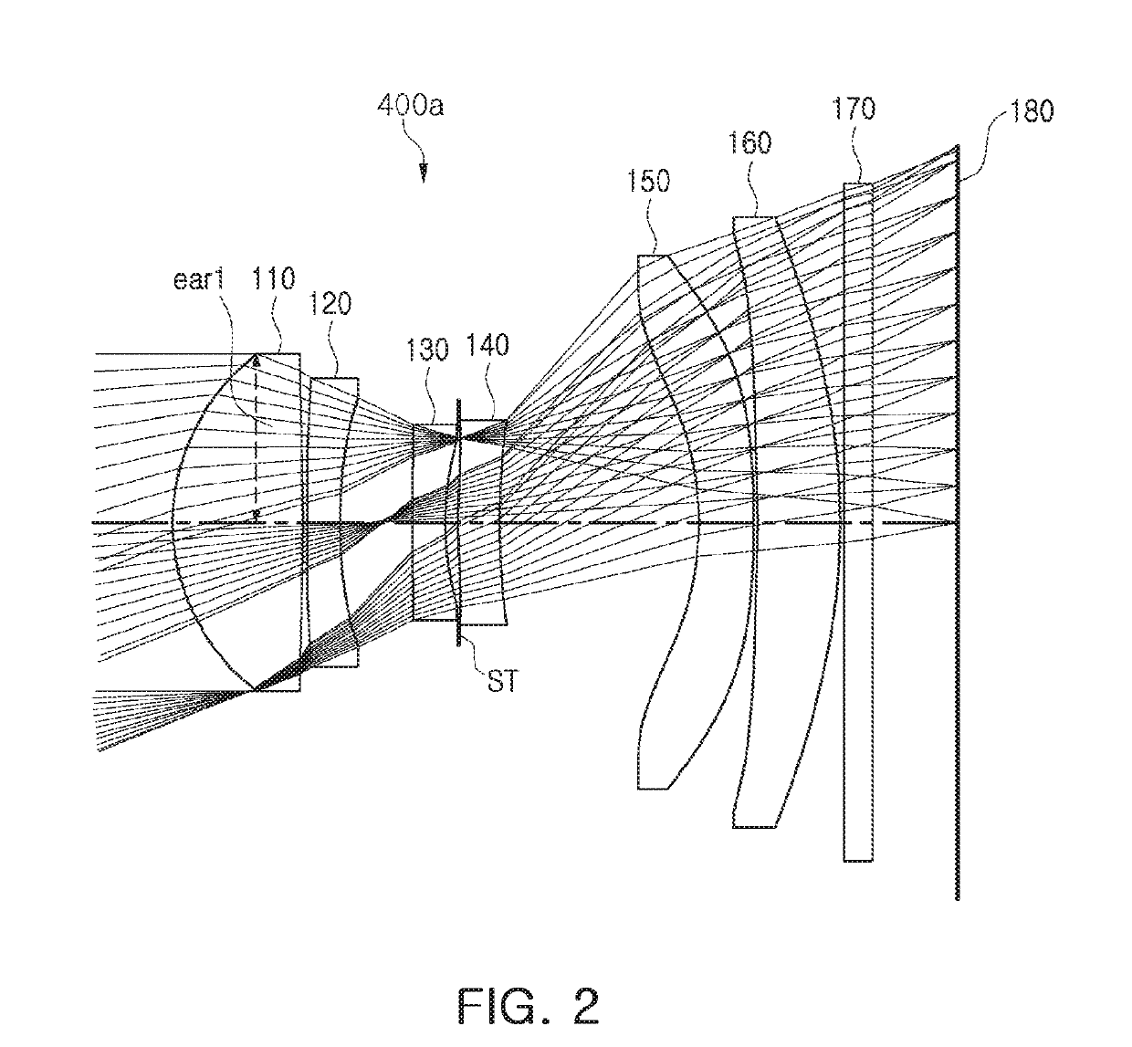
An optical imaging system includes a first lens, a second lens, a third lens, a fourth lens, a fifth lens, and a sixth lens sequentially disposed on an optical axis from an object side toward an image side. A distance from an object-side surface of the first lens to an imaging plane of an image sensor is TTL, an overall focal length of an optical system including the first to sixth lenses is F, and TTL/F≤0.83. An optical axis distance between the second lens and the third lens is D23, an optical axis distance between the third lens and the fourth lens is D34, and 2.2<D23/D34<5.4.

Description

CROSS-REFERENCE TO RELATED APPLICATIONS[0001]This application claims the benefit under 35 USC 119(a) of Korean Patent Application No. 10-2017-0141370 filed on Oct. 27, 2017, in the Korean Intellectual Property Office, the entire disclosure of which is incorporated herein by reference for all purposes.BACKGROUND1. Field[0002]This application relates to an optical imaging system.2. Description of the Background[0003]Recently, mobile communications terminals have been provided with camera modules, enabling video calling and image capturing. As the utilization of camera modules mounted in mobile communications terminals has increased, camera modules for mobile communications terminals have gradually been required to have higher resolution and performance.[0004]Because there is also a trend to gradually miniaturize and lighten mobile communications terminals, there may be limitations in realizing camera modules having high resolution and performance.[0005]In addition, a telephoto lens ha...

Claims


Application Information

Patent Timeline
Patent Type & Authority Applications(United States)
IPC IPC(8): G02B13/00G02B9/62H04N5/225G02B13/02
CPCG02B13/0045G02B9/62H04N5/2254G02B13/02G02B13/0015G03B30/00G02B1/041H04N23/55
Inventor SON, JU HWAJIN, YOUNG SUYANG, DONG SHINJO, YONG JOO
Owner SAMSUNG ELECTRO MECHANICS CO LTD
Why Eureka
Try Eureka