Cordless Soldering Iron

a soldering iron and cordless technology, applied in the direction of soldering equipment, metal-working equipment, manufacturing tools, etc., can solve the problems of user fatigue, large changes in the temperature of the tip during the soldering process, and cords may interfere with the soldering of another person

Active Publication Date: 2019-05-09
HAKKO CO LTD
View PDF0 Cites 9 Cited by
  • Summary
  • Abstract
  • Description
  • Claims
  • Application Information

AI Technical Summary

Problems solved by technology

Sometimes the cable connecting the soldering iron to the control station gets in the way of the work and the cord may also interfere with another person's soldering if two workers sit next to each other.
The extra weight of the battery for the present cordless soldering irons make them heavy, and repetitive use of a heavy hand tool in the industrial soldering environment makes the user tired.
For example, conventional cordless soldering irons generally do not h

Method used


Image

  • Cordless Soldering Iron
  • Cordless Soldering Iron
  • Cordless Soldering Iron

Examples


Embodiment Construction

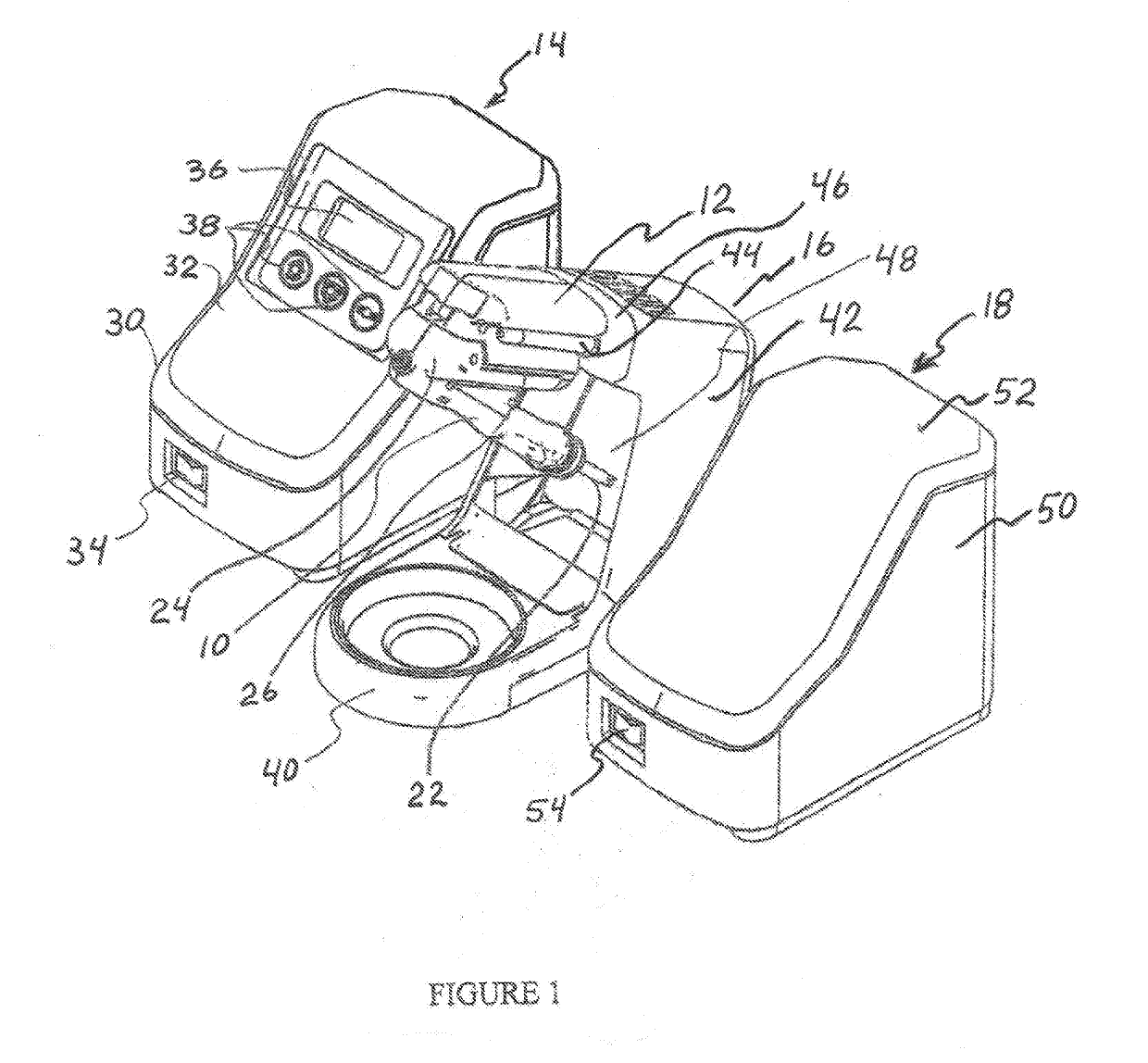
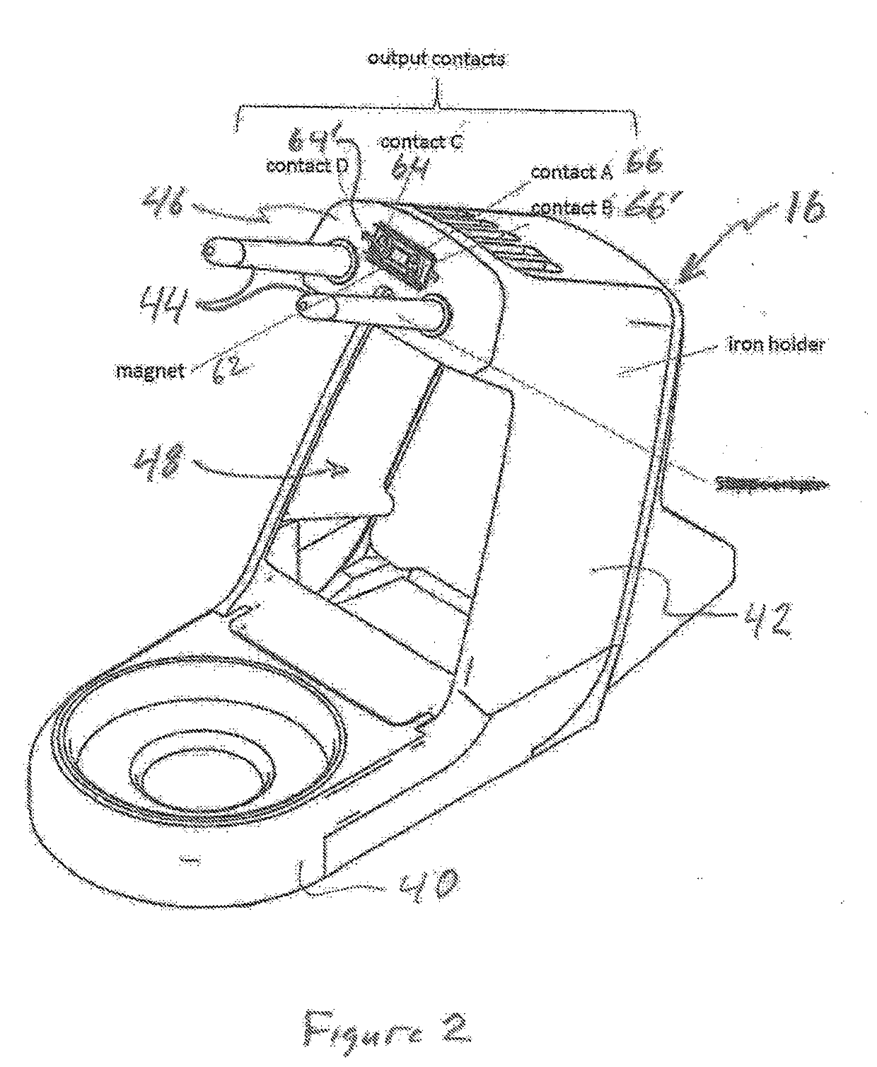
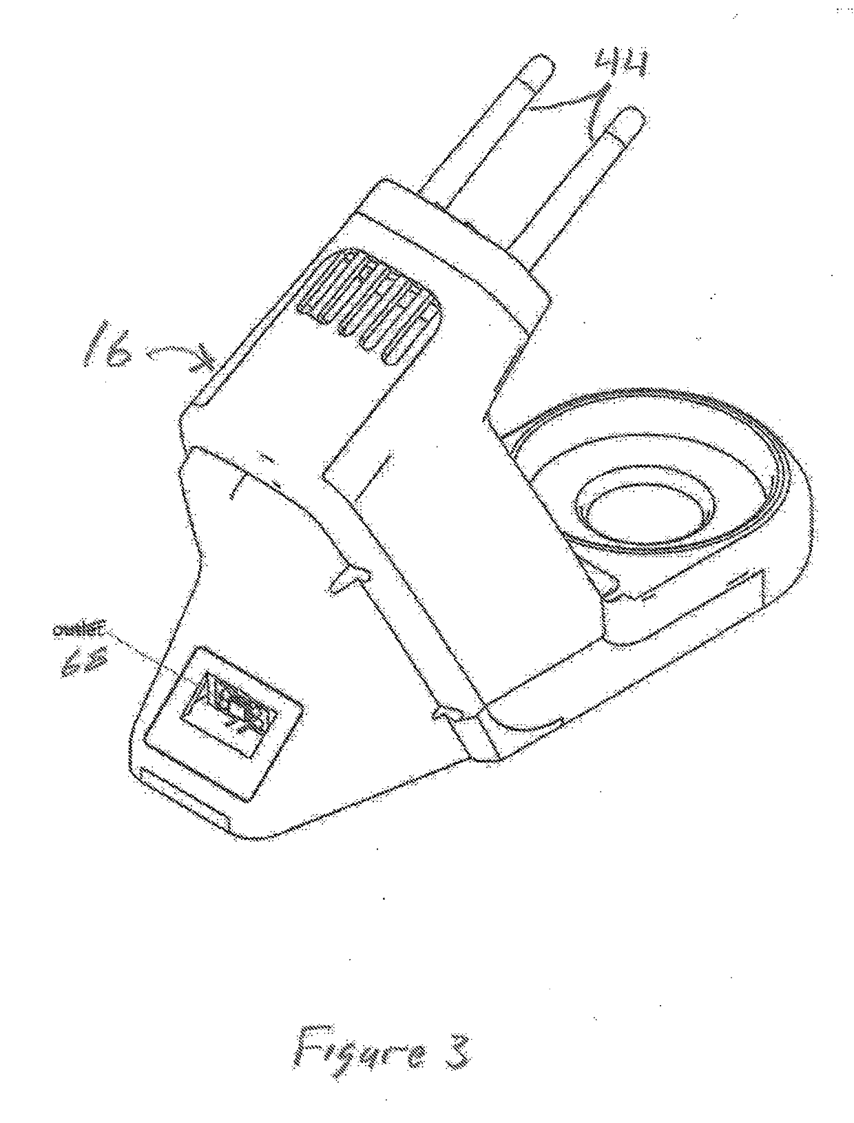
[0020]FIG. 1 is a perspective view of the cordless soldering iron 10, associated battery 12, a control station 14, a soldering iron holder 16 which may include a soldering iron power supply and battery charger functionality, and a charge station 18. The cordless soldering iron 10 includes a soldering iron cartridge 22 and a grip 24 having an integral base 26 configured to allow removable attachment to an ergonomically compatible power supply battery pack 28 containing the battery 12. The battery 12 is preferably a rechargeable battery. The power supply battery pack may have a shape allowing the recharging of the battery 12 with a power tool battery charger.

[0021]The control station 14 includes a housing 30 with a front panel 32 on the upper top surface of the housing 30. A power switch 34 may be positioned on the front of the housing 30 as shown in FIG. 1, or the power switch could be positioned on the front panel 32. The front panel 32 preferably includes a display 36, for example ...


PUM


Abstract

A cordless, hand held soldering iron operable with a control station providing wireless temperature control functionality and a charging station.

Description

FIELD OF THE INVENTION[0001]The present invention relates to the field of soldering devices and more particularly to a cordless soldering iron and associated control station providing wireless control of the operation of the soldering iron, and a battery charging station operative with the cordless soldering iron.BACKGROUND AND RELATED ART[0002]Present industrial or factory soldering stations typically include a control station that connects to a soldering iron via a cable. Sometimes the cable connecting the soldering iron to the control station gets in the way of the work and the cord may also interfere with another person's soldering if two workers sit next to each other. To address the limitations of the cable connecting the soldering iron to a control station some cordless soldering irons have been developed. Usually cordless soldering irons have a battery so that they tend to be larger than the hand held soldering irons having a cord connected to a control station. The extra we...

Claims


Application Information

Patent Timeline
IPC IPC(8): B23K3/03
CPCB23K3/0323B23K3/033B23K3/02B23K3/03B23K3/08Y02E60/10
Inventor TERAOKA, YOSHITOMONAKAMURA, KENTA
Owner HAKKO CO LTD
Why Eureka
Try Eureka