
Sunlight focusing analysis device for vehicle lamp lens, and method for using same

a technology of focusing analysis and vehicle lamps, which is applied in the direction of instruments, lighting and heating equipment, transportation and packaging, etc., can solve the problems of reducing the degree of damag

Active Publication Date: 2019-05-09
HASCO VISION TECHNOLOGY CO LTD
View PDF0 Cites 3 Cited by
  • Summary
  • Abstract
  • Description
  • Claims
  • Application Information

AI Technical Summary

Benefits of technology

This patent is about a device and method for analyzing the performance of vehicle lamps. The device uses sunlight to simulate damage caused by sunlight focused by different lenses. It can rotate the lens and lamp to observe and analyze the effects of sunlight from different angles. The device can also adapt to different platform angles and can be adjusted to face sunlight. Additionally, the device can accommodate different lens sizes and shapes. The technical effects of the patent are that it provides a reliable and efficient tool for analyzing and testing vehicle lamps, and can help identify potential defects.

Problems solved by technology

While the optical requirement has been met, an unexpected problem that peripheral parts of the lenses of the lamps are prone to ablation is fed back from the aftermarket.
Through analysis, the reason for such ablation is that a high temperature in a small area is caused by focal spots formed on the peripheries of the lenses after sunlight is refracted and totally reflected by the lenses, consequentially, resulting in melting or ablation of the lamps and the peripheral plastic parts of the lamps.
However, ablation of the peripheral parts of the vehicle lens is accidentally caused by sunlight, deviating from a designed projection optical axis of the vehicle lens, focused by the vehicle lens outside the optical axis, and the ablated part and the degree of damage are random and depend on the parking direction of vehicles and the intensity of sunlight.
The above-mentioned existing technical scheme for analyzing and measuring the focal spot formed by sunlight passing through the optical axis of the lens cannot be used for the observation, analysis and verification of ablation of automotive lamp parts around the lens caused by focused sunlight due to the fact that such scheme entirely fails to take focusing outside the optical axis of the vehicle lens into consideration.

Method used


Image

  • Sunlight focusing analysis device for vehicle lamp lens, and method for using same
  • Sunlight focusing analysis device for vehicle lamp lens, and method for using same
  • Sunlight focusing analysis device for vehicle lamp lens, and method for using same

Examples


Embodiment Construction

[0045]For a better understanding of the above technical scheme of the invention, the invention is further described in detail as follows in combination with the drawings and embodiments.

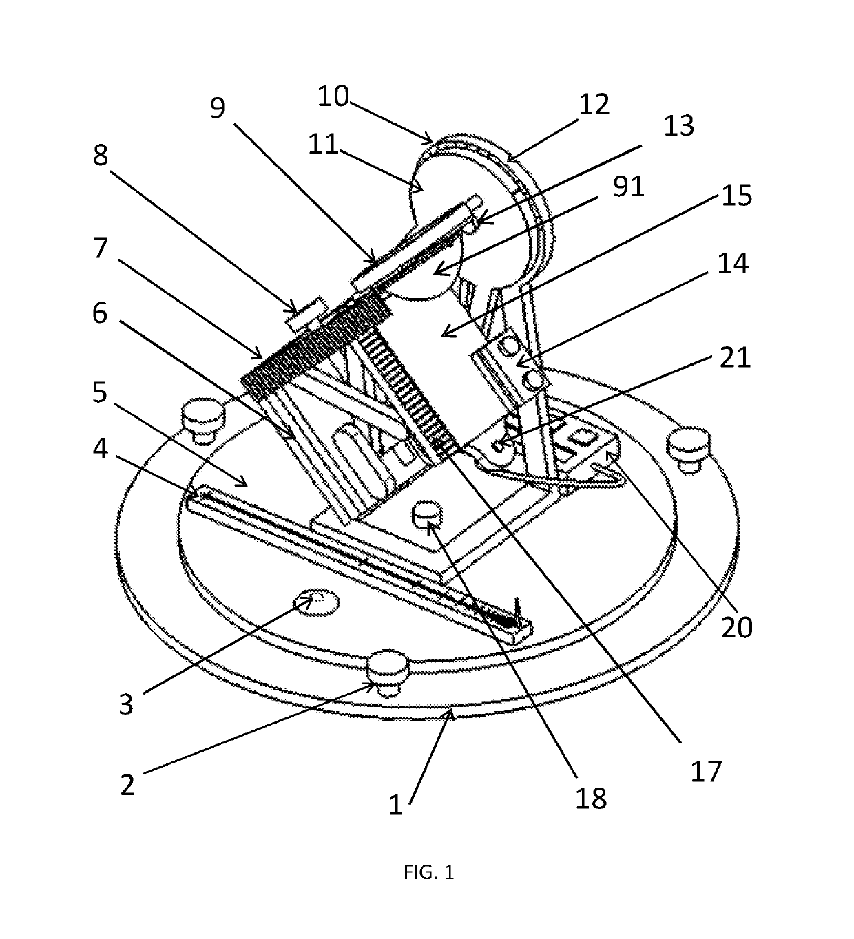
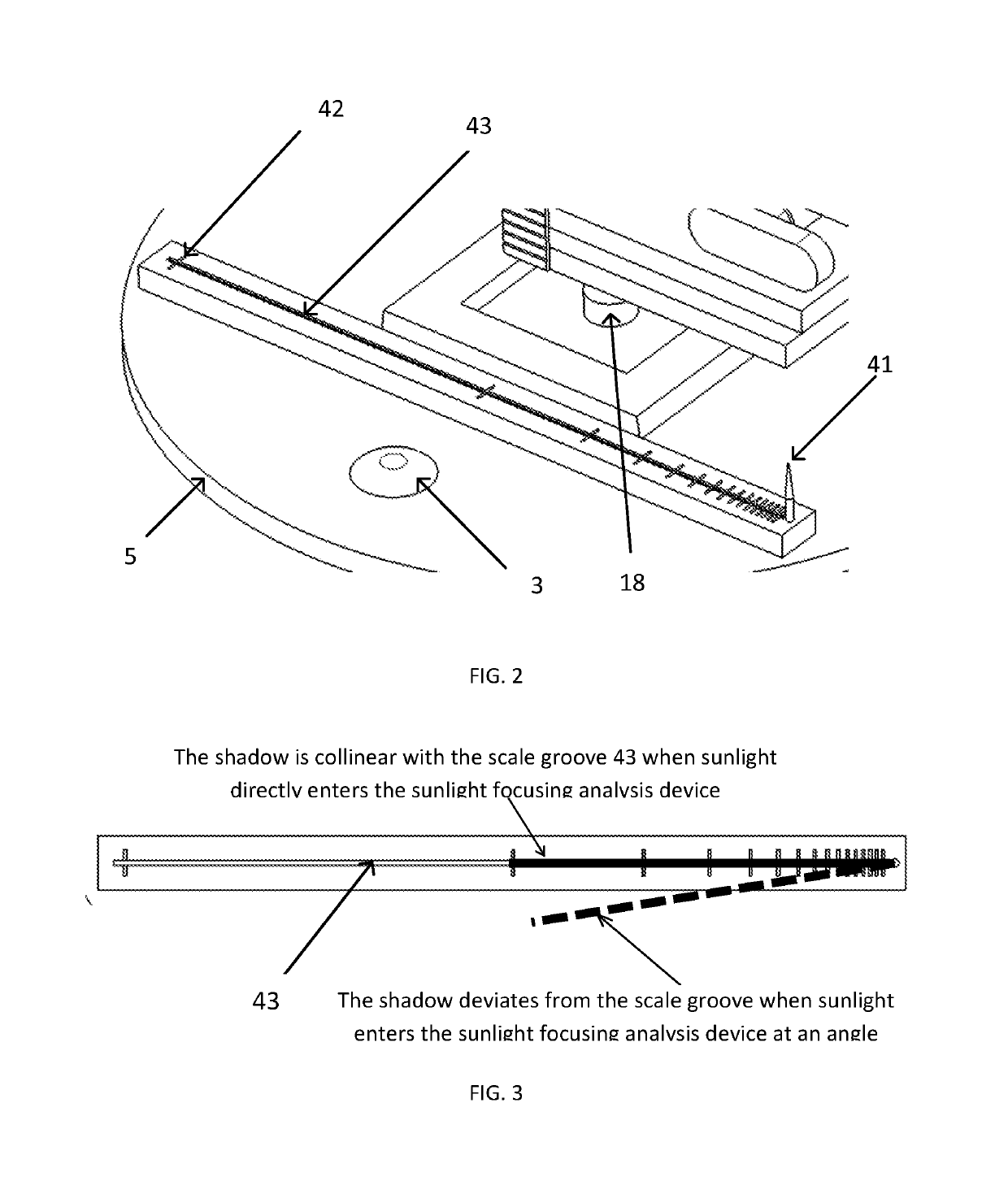
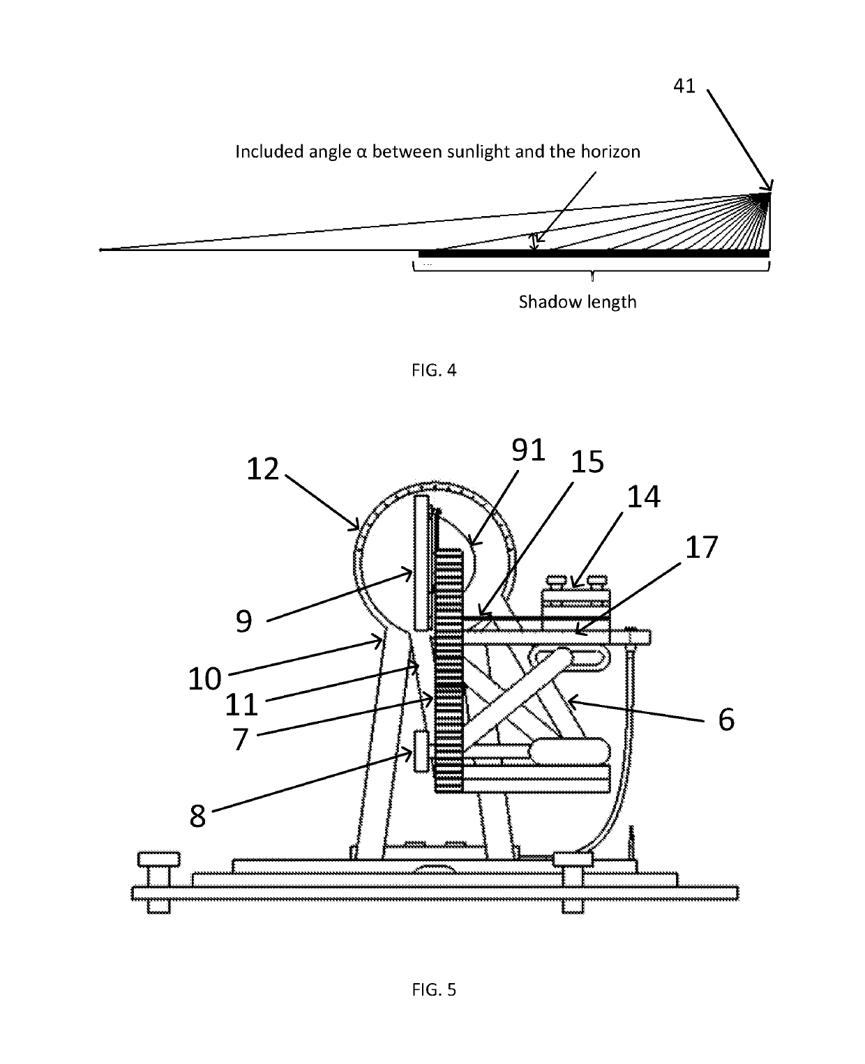
[0046]As shown in FIG. 1 and FIG. 12, in one embodiment, the sunlight focusing analysis device for a vehicle lamp lens comprises an adjustable horizontal base 1, a lens holder 9 used to clamp a vehicle lamp lens 91, and a test piece holder 14 used to hold a test piece 15. A horizontal rotary table 5 capable of rotating around a rotating shaft 18 and an inclination angle adjustment mechanism arranged in the middle of the horizontal rotary table 5 are provided on the base 1. The inclination angle adjustment mechanism is formed by a fixed support arm 10 and a vertical swing arm 11 connected to each other. The fixed support arm 10 is fixedly connected to the horizontal rotary table 5. The vertical swing arm 11 is rotatably connected to the fixed support arm 10 through a swing arm shaft 13. The lens holde...


PUM


Abstract

A sunlight focusing analysis device relating to an analysis and verification device for a potential failure mode of a vehicle lamp projection unit, and a method for using same, and in particular to the analysis and verification of ablation of peripheral parts of a lens caused by focal spots formed by sunlight focused via a vehicle lamp lens. The device comprises a base, a lens holder, and a test piece holder. A horizontal rotary table and an inclination angle adjustment mechanism are provided on the base; the inclination angle adjustment mechanism is formed by a fixed support arm and a vertical swing arm connected to each other; the lens holder is fixed on the vertical swing arm; the test piece holder is mounted on a test piece lifting platform below the lens holder.

Description

BACKGROUND OF THE INVENTIONTechnical Field[0001]The invention relates to an analysis and verification device for a potential failure mode of a vehicle lamp projection unit and a method for using same, in particular to the analysis and verification of ablation of peripheral parts of a lens caused by focal spots formed by sunlight focused via a vehicle lamp lens.Description of Related Art[0002]With the development of automotive lamps, projection units are increasingly applied to automotive headlamps to realize high and low beams. As an important constituent part of the projection units, lenses with different sizes and focal distances have been designed to meet different function and shape requirements. While the optical requirement has been met, an unexpected problem that peripheral parts of the lenses of the lamps are prone to ablation is fed back from the aftermarket. Through analysis, the reason for such ablation is that a high temperature in a small area is caused by focal spots f...

Claims


Application Information

Patent Timeline
Patent Type & Authority Applications(United States)
IPC IPC(8): F21S41/29F21S41/25F24S23/30G01M11/06
CPCF21S41/295F21S41/25F24S23/30G01M11/06G01M11/02G01N17/00Y02E10/40
Inventor CHEN, MINGMINZHOU, SONGJIE
Owner HASCO VISION TECHNOLOGY CO LTD
Learn More