3D skeletonization using truncated epipolar lines

a skeletonization and 3d technology, applied in 3d modeling, image enhancement, instruments, etc., can solve the problems of difficult to determine whether two images depict the same feature of an object from different perspectives, epipolar lines may not be effective for identifying correlated features, and difficult to create three-dimensional (3d) representations of objects from two-dimensional (2d) images

Active Publication Date: 2019-05-09
MICROSOFT TECH LICENSING LLC
View PDF6 Cites 32 Cited by
  • Summary
  • Abstract
  • Description
  • Claims
  • Application Information

AI Technical Summary

Benefits of technology

[0004]This Summary is provided to introduce a selection of concepts in a simplified form that are further described below in the Detailed Description. This Summary i...

Problems solved by technology

Creating a three-dimensional (3D) representations of objects from two-dimensional (2D) images can be a difficult task.
However, it can be difficult to determine whether two images depict a same feature of an object from different perspectives.
However, in complex scenes, or...

Method used


Image

  • 3D skeletonization using truncated epipolar lines
  • 3D skeletonization using truncated epipolar lines
  • 3D skeletonization using truncated epipolar lines

Examples


example implementations

[0102]Although the operations of some of the disclosed methods are described in a particular, sequential order for convenient presentation, it should be understood that this manner of description encompasses rearrangement, unless a particular ordering is required by specific language set forth below. For example, operations described sequentially may in some cases be rearranged or performed concurrently. Moreover, for the sake of simplicity, the attached figures may not show the various ways in which the disclosed methods can be used in conjunction with other methods.

[0103]Any of the disclosed methods can be implemented as computer-executable instructions or a computer program product stored on one or more computer-readable storage media and executed on a computing device (i.e., any available computing device, including smart phones or other mobile devices that include computing hardware). Computer-readable storage media are tangible media that can be accessed within a computing env...


PUM


Abstract

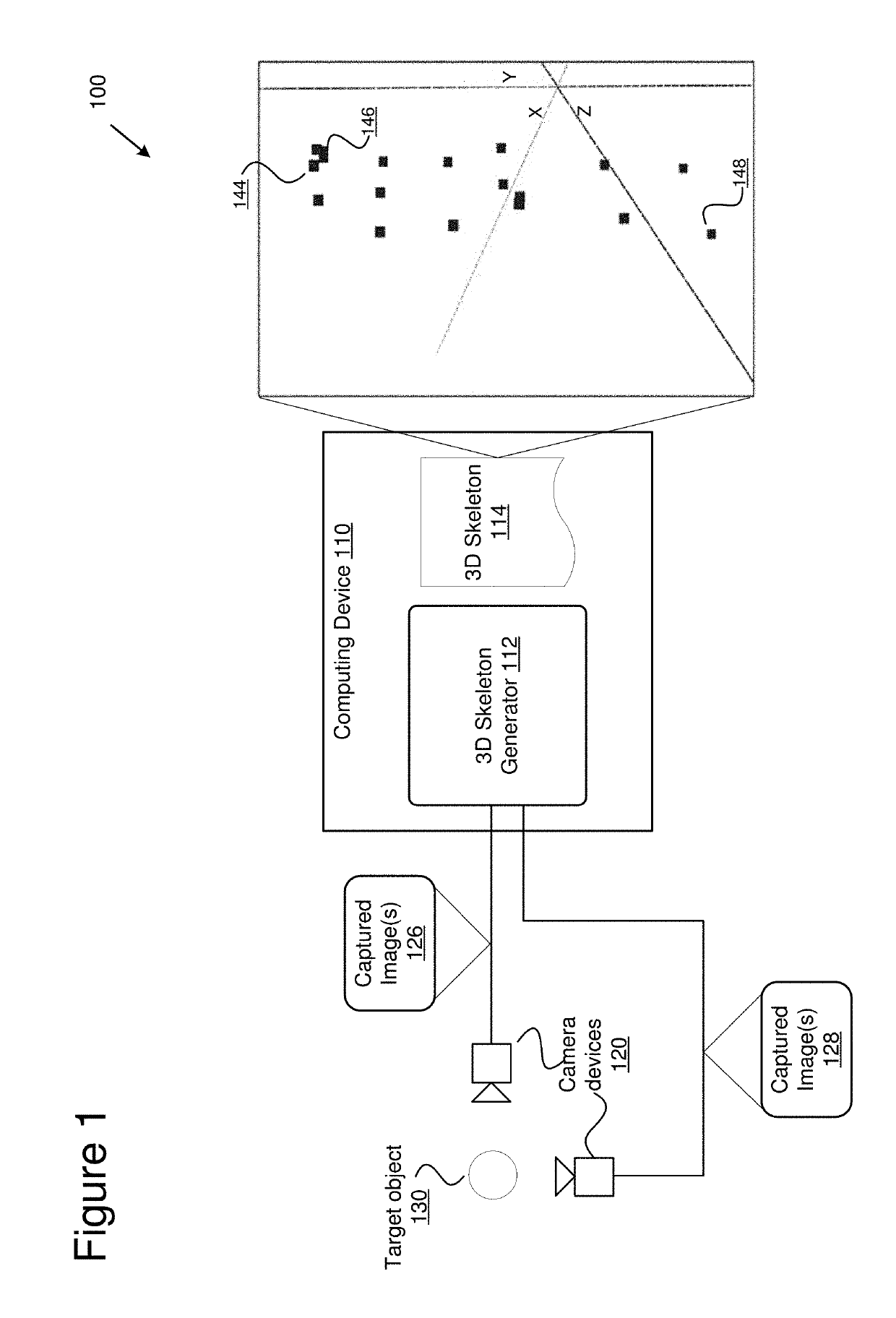
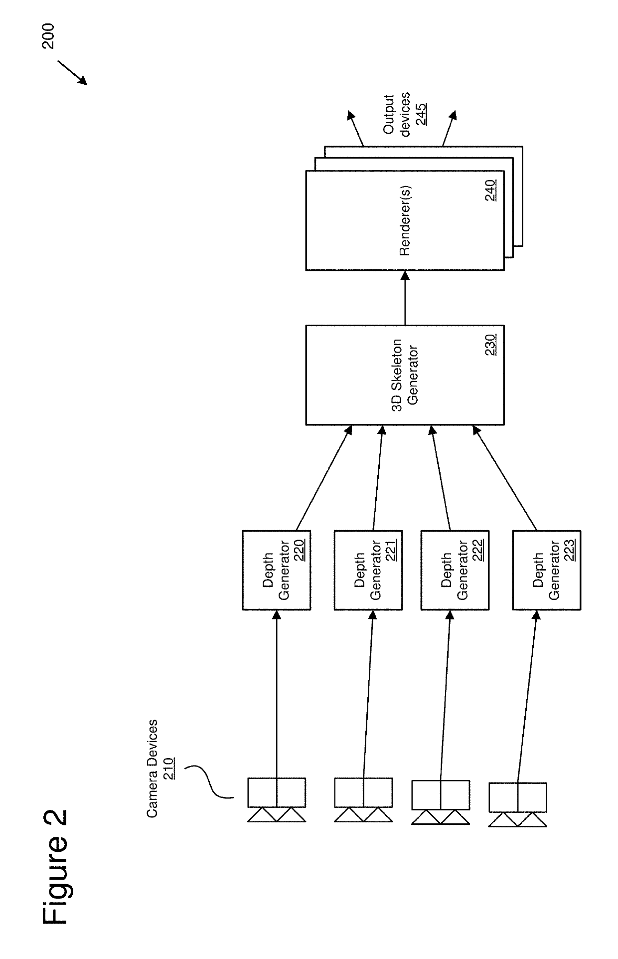
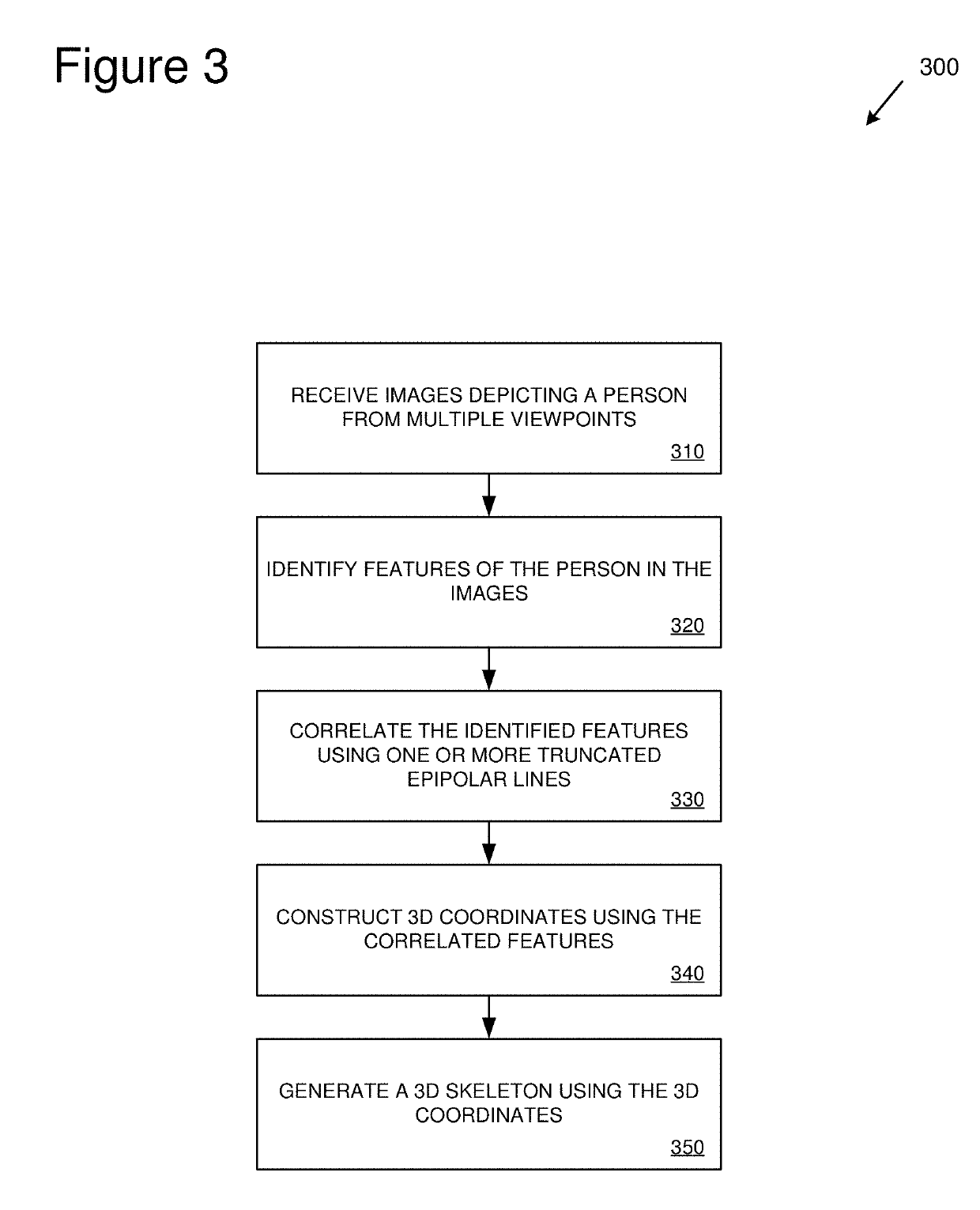
Technologies are provided for generating three-dimensional (3D) skeletons of target objects using images of the target objects captured from different viewpoints. Images of an object (such as a person) can be captured from different camera angles. Feature keypoints of the object can be identified in the captured images. Keypoints that identify a same feature in separate images can be correlated using truncated epipolar lines. For example, depth information for a keypoint can be used to truncate an epipolar line that is created using the keypoint. The correlated feature keypoints can be used to create 3D feature coordinates for the associated features of the object. A 3D skeleton can be generated using the 3D feature coordinates. One or more 3D models can be mapped to the 3D skeleton and rendered. The rendered one or more 3D models can be displayed on one or more display devices.

Description

BACKGROUND[0001]Creating a three-dimensional (3D) representations of objects from two-dimensional (2D) images can be a difficult task. For example, creating the 3D representation can require inferring 3D features of the object based on 2D features depicted in the images. However, it can be difficult to determine whether two images depict a same feature of an object from different perspectives.[0002]In some solutions, points in separate 2D images are correlated using an epipolar line. A feature point in one image can be used to project an epipolar line onto another image. A feature point in the other image intersected by the epipolar line may be correlated with the feature point used to project the line. However, in complex scenes, or scenes involving multiple objects, epipolar lines may not be effective for identifying correlated features. In at least some cases, an epipolar line can bisect a large area of an image, multiple candidate feature points may be intersected by the line. I...

Claims


Application Information

Patent Timeline
IPC IPC(8): G06T15/20H04N13/02G06T15/04G06T17/20G06V10/40G06V10/75
CPCH04N13/204H04N13/271G06T15/205G06T15/04G06T17/20G06K9/00362G06K9/46G06T19/20G06T2219/2021G01B11/245G06T7/593G06T2207/10012G06T2207/30196G06V20/64G06V40/10G06V10/40G06V10/75H04N23/60H04N23/90G06F18/22G06T7/00
Inventor CHEN, QIUYU
Owner MICROSOFT TECH LICENSING LLC
Why Eureka
Try Eureka