Compact Electronic and Manual Lock Drive System

a technology of electronic and manual locks and drive systems, applied in the direction of latching locks, non-mechanical controls, construction fastening devices, etc., can solve the problem of bulky modules on either side of the door

Inactive Publication Date: 2019-05-16
SIVLS INC
View PDF10 Cites 7 Cited by
  • Summary
  • Abstract
  • Description
  • Claims
  • Application Information

AI Technical Summary

Benefits of technology

[0005]The objective of the present invention to provide an easy-to-install and compact electronic and manual lock drive system which provide both motorized and manual operation of the lock.

Problems solved by technology

Although various approaches have been developed to combine these different mechanisms and functions in a single device, most systems involve many mechanical and electronic components resulting in a bulky module on either side of the door.

Method used


Image

  • Compact Electronic and Manual Lock Drive System
  • Compact Electronic and Manual Lock Drive System
  • Compact Electronic and Manual Lock Drive System

Examples


Embodiment Construction

[0057]In the detailed description, numerous specific details are set forth in order to provide a thorough understanding of the invention. However, it will be understood by those skilled in the art that these are specific embodiments, and that the present invention may be practiced also in different ways that embody the characterizing features of the invention as described herein. Additionally, some well-known structures or functions may not be shown or described in detail, so as to avoid unnecessarily obscuring the relevant description of the various embodiments.

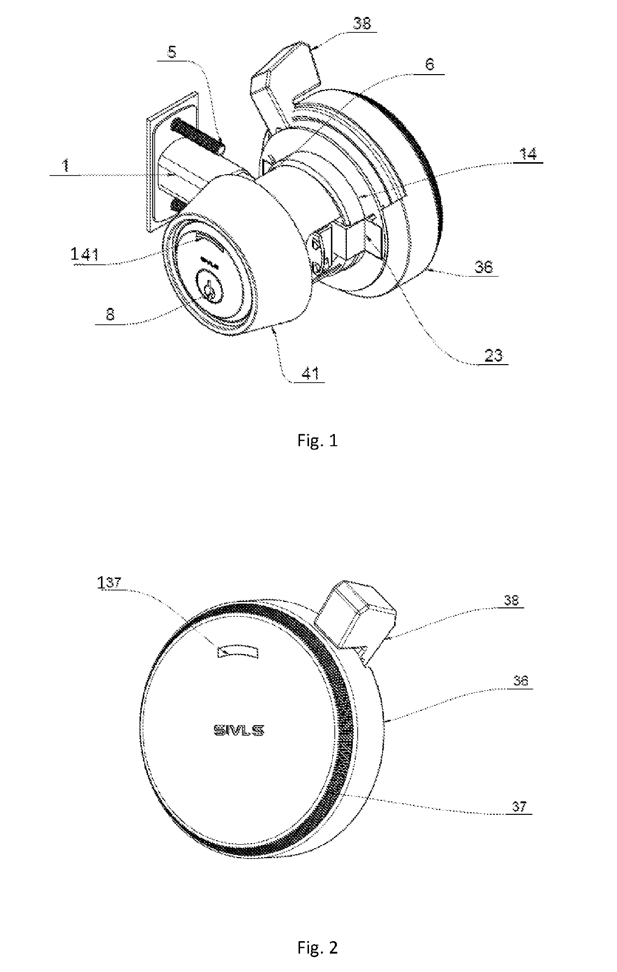
[0058]FIG. 1 illustrates an embodiment of the electronic and mechanical drive system working with a key cylinder and deadbolt door lock. In this assembly, the key access portion, including the key cylinder 8 and key cylinder housing 41, is installed on one side of the door (door not shown in this figure). There is a front LED (light emitting diode) indicator 141 on the front face of the key cylinder housing 41. This can be u...


PUM


Abstract

The present invention is an electronic and manual lock drive system providing both motorized and manual operation of a door lock. The electronic drive system has a compact design and can be mostly fit in the through-door space. It is combined with manual operation module using a lever for moving the deadbolt. The coupling and decoupling of the electromechanical drive system and the manual operation module is achieved by an offset in the rotational axis of the driving gear and the lever handle rotation as well as clutch elements located on the gear and the lever handle. The electronic and manual drive system also comprises a function to provide inform on the state of the lock. This is accomplished by using a pair of sensor switches.

Description

REFERENCE TO RELATED APPLICATIONS[0001]This is a first-filed invention.BACKGROUND OF THE INVENTION[0002]The present invention is in the technical field of electrically operated door locks. More particularly, the present invention relates to a drive apparatus for motor and manual operation of door locks.[0003]Many designs of remote-controlled electronic door locks have been developed to provide convenience and security to users. Usually the electrical operation of a door lock involves extending and retracting a latch bolt or a deadbolt of the door lock using a motorized mechanism. In many products, the motorized mechanism of an electronic door lock is combined with traditional mechanisms using a key cylinder and door knobs / handles, so that the users have the option to lock and unlock using a key or by turning a door knob / handle. In addition, it is desirable to inform the user of the state of the lock (locked or unlocked) using indicators on the device or wirelessly transmitting the i...

Claims


Application Information

Patent Timeline
Patent Type & Authority Applications(United States)
IPC IPC(8): E05B47/00E05B17/22E05B63/00E05B47/02E05C1/00
CPCE05B47/0012E05B17/22E05B63/0056E05B47/02E05C1/004E05B55/12E05B2047/002E05B41/00E05B47/026E05B2047/0026E05B2047/0067E05B2047/0069
Inventor AFFAN, MAJEDWIEGANDT, NESTORIUS
Owner SIVLS INC
Why Eureka
Try Eureka