
High pressure pump

Active Publication Date: 2019-05-16
DENSO CORP
View PDF22 Cites 1 Cited by
  • Summary
  • Abstract
  • Description
  • Claims
  • Application Information

AI Technical Summary

Benefits of technology

The present patent aims to provide a compact high pressure pump that reduces pressure pulsation in a fuel chamber and can be easily installed in an internal combustion engine. The fuel chamber forming portion is placed at a location that is displaced from the axis of the receiving through-hole, making it hard for the tool used to fix the pump to interfere with the chamber. This eases the installation process. The size of the chamber can be increased without interfering with the tool, thus providing better results. Additionally, the fuel chamber forming portion is placed on the radially outer side of the plunger, minimizing interference with the through-hole. Overall, this design helps reduce fuel pulsation and improves the performance of the high pressure pump.

Problems solved by technology

Therefore, in a case where an outer diameter of a fuel chamber forming portion, which forms the fuel chamber, or an outer diameter of the pulsation damper is larger than a distance between the two through-holes, a tool, which is used to threadably fix the fixing members to the internal combustion engine, may possible interfere with the fuel chamber forming portion, and thereby the installation of the high pressure pump to the internal combustion engine may possibly become difficult.
Therefore, there is a possibility of that sufficient damping effect for damping the pressure pulsation cannot be achieved.
In this way, the size of the high pressure pump may be disadvantageously increased.

Method used


Image

  • High pressure pump
  • High pressure pump
  • High pressure pump

Examples


first embodiment

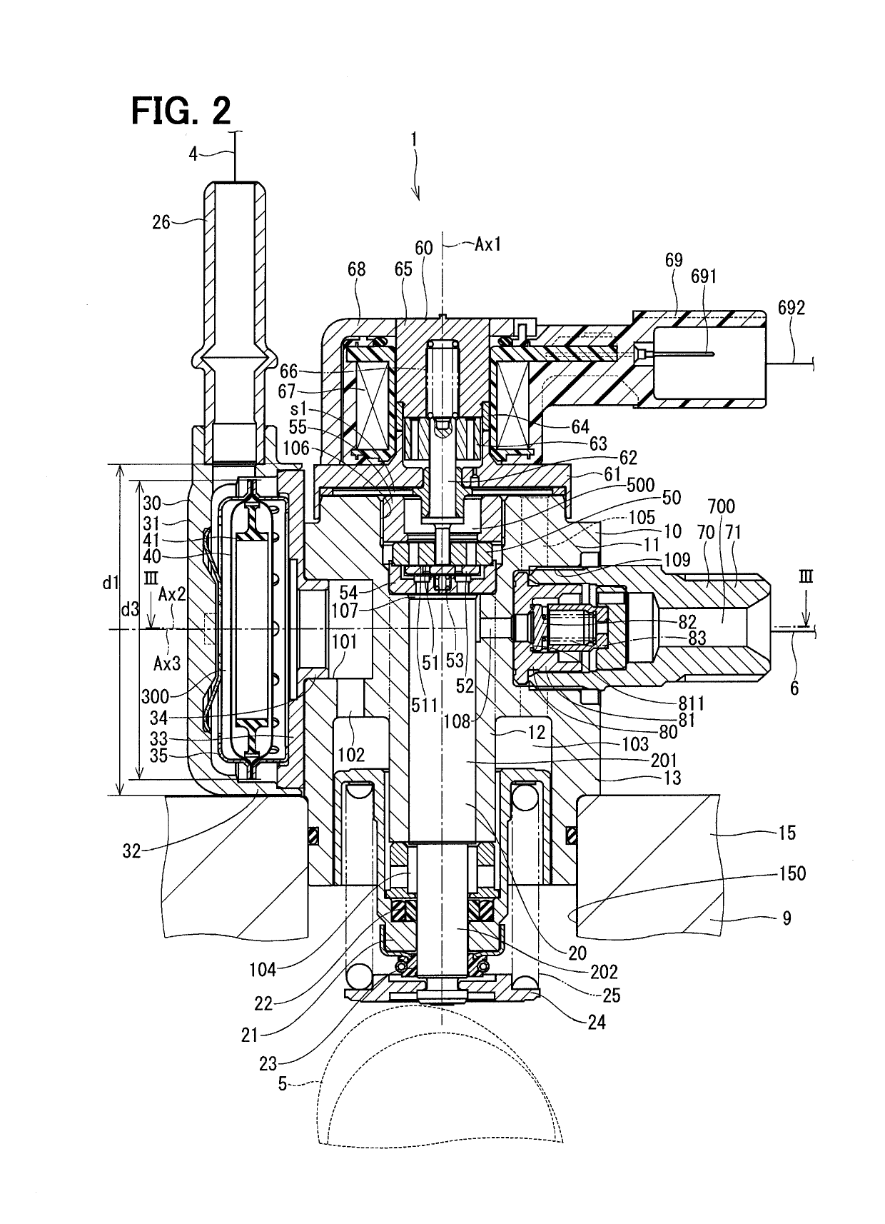
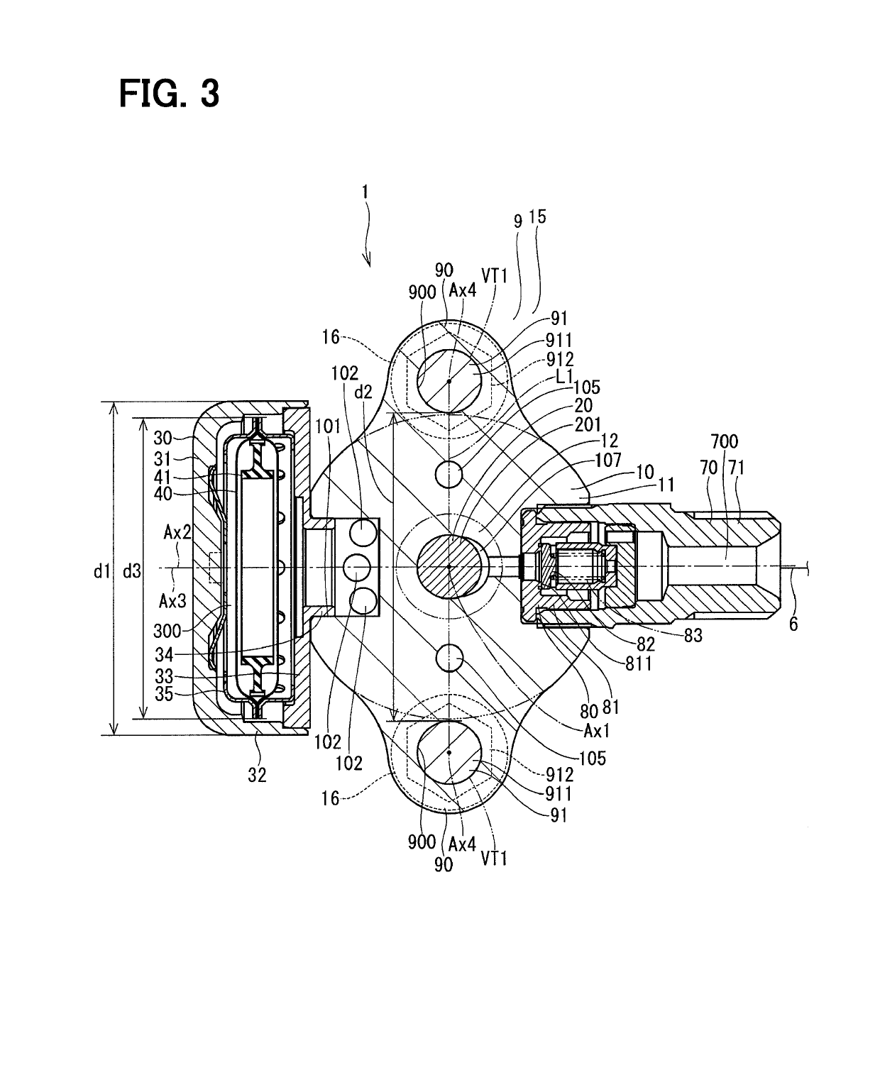
[0035]FIGS. 2 and 3 show a high pressure pump according to a first embodiment of the present disclosure.

[0036]The high pressure pump 1 is installed to a vehicle (not shown). The high pressure pump 1 is a pump that supplies the fuel at a high pressure to, for example, an engine 9 that serves as an internal combustion engine. The fuel, which is supplied from the high pressure pump 1 to the engine 9, is, for example, gasoline. That is, a fuel supply subject of the high pressure pump 1 is a gasoline engine.

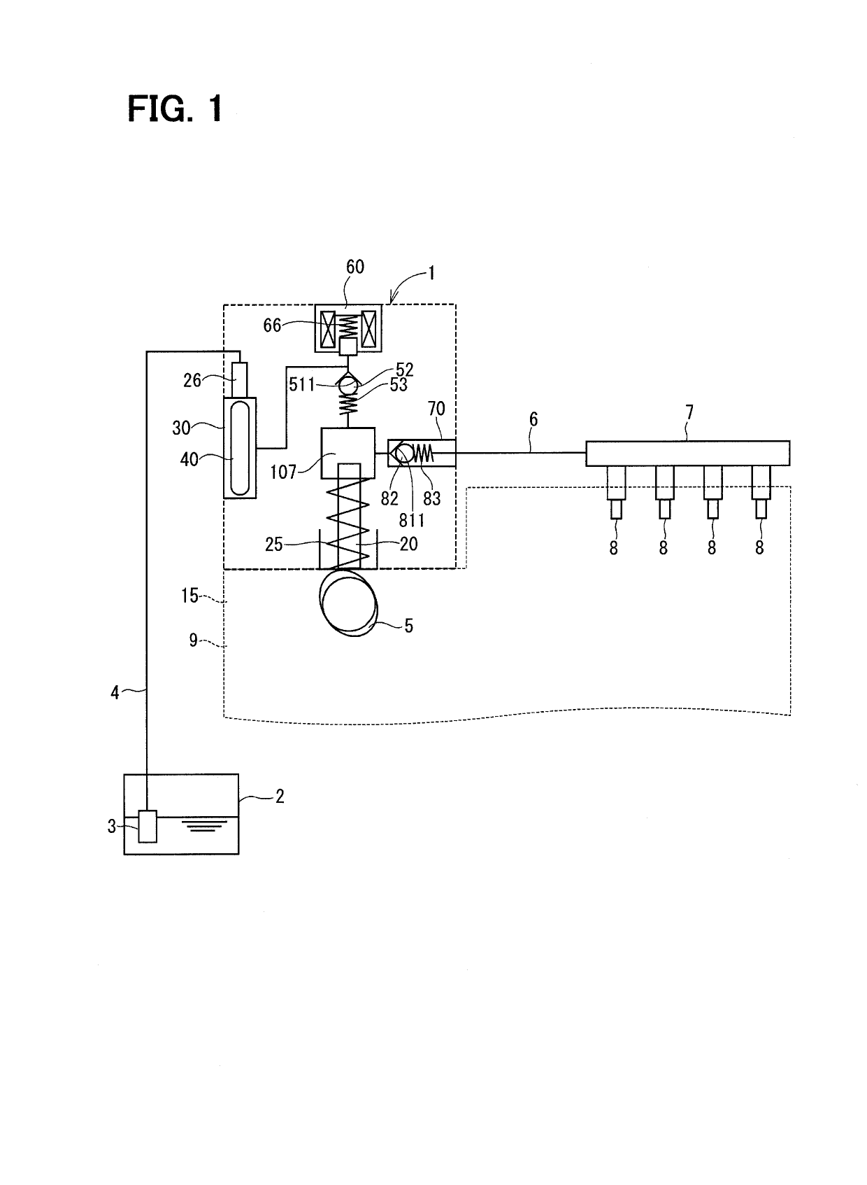
[0037]As shown in FIG. 1, the fuel, which is stored in a fuel tank 2, is supplied from a fuel pump 3 to the high pressure pump 1 through a pipe 4. The high pressure pump 1 pressurizes the fuel supplied from the fuel pump 3 and discharges the pressurized fuel to a fuel rail 7 through a pipe 6. Thereby, the fuel in the fuel rail 7 is accumulated under the pressurized state and is injected at the engine 9 from fuel injection valves 8 connected to the fuel rail 7.

[0038]As shown in FIGS. 2...

second embodiment

[0150]FIG. 6 shows a portion of the high pressure pump according to a second embodiment of the present disclosure. The second embodiment differs from the first embodiment with respect to the structure of fixing members that fix the fixable portions 90 to the engine 9.

[0151]In the second embodiment, shaft portions 152 are formed at the engine head 15 of the engine 9. The shaft portions 152 are formed integrally as one piece with the engine head 15 such that the shaft portions 152 respectively extend from the engine head 15 in a generally cylindrical column form. The shaft portion 152 is formed such that an axis of the shaft portion 152 is generally parallel to the axis of the installation hole portion 150. A male thread is formed at an outer wall of an opposite end part of each shaft portion 152, which is opposite from the engine head 15.

[0152]In the present embodiment, each of the fixable portions 90 is fixed to the engine head 15 by a nut 92, which is provided to correspond with th...

third embodiment

[0157]FIG. 7 shows a high pressure pump according to a third embodiment of the present disclosure. A position of the fuel chamber forming portion 30 is different from that of the first embodiment.

[0158]In the third embodiment, there is further provided a relief valve device 85. The relief valve device 85 is installed to the outer wall of the housing main body 11 of the housing 10. In the present embodiment, the relief valve device 85 is placed to project form the outer wall of the housing main body 11 in a direction that is generally parallel to the axis Ax1 of the plunger 20. The relief valve device 85 includes, for example, a relief valve (not shown). The relief valve is placed such that the relief valve can open and close a passage that connects between an opposite side of the discharge valve seat 811, which is in the inside of the discharge tubular portion 71 of the discharge portion 70 and is opposite from the pressurizing chamber 107, and the gap s1 (see FIG. 2) between the ho...


PUM


Abstract

A housing-includes a pressurizing chamber. A plunger is moved to increase and decrease a volume of the pressurizing chamber, so that the plunger can pressurize the fuel in the pressurizing chamber. A fuel chamber forming portion is placed on a radially outer side of the plunger and forms a fuel chamber that is communicated with the pressurizing chamber. A pulsation damper is placed in an inside of the fuel chamber and is operable to reduce pressure pulsation of the fuel in the fuel chamber. Fixable portions are placed on a radially outer side of the plunger while each of the fixable portions includes a receiving through-hole. The fixable portions are fixed to an engine with bolts, which are provided to correspond with the receiving through-holes, respectively. The fuel chamber forming portion is displaced from axes of the receiving through-holes.

Description

CROSS REFERENCE TO RELATED APPLICATION[0001]This application is based on and incorporates herein by reference Japanese Patent Application No. 2016-90327 filed on Apr. 28, 2016.TECHNICAL FIELD[0002]The present disclosure relates to a high pressure pump that pressurizes fuel and discharges the pressurized fuel.BACKGROUND ART[0003]Previously, there is known a high pressure pump to be installed to an internal combustion engine while the high pressure pump pressurizes fuel and supplies the pressurized fuel to the internal combustion engine. For example, the high pressure pump of the patent literature 1 includes fixable portions that project outwardly from an outer wall of a housing and are fixed to the internal combustion engine. Each of the fixable portions includes a through-hole that has an axis, which is parallel to an axis of a plunger. Fixing members are respectively inserted through the through-holes and are threadably fixed to the internal combustion engine, so that the fixable p...

Claims


Application Information

Patent Timeline
IPC IPC(8): F02M55/04F02M59/36F02M59/46
CPCF02M55/04F02M59/36F02M59/46F02M55/008F02M2200/30F02M55/00F02M59/44F04B11/0091F02M59/102F04B11/0016F04B53/16F04B1/0404F02M59/48F02M2200/315
Inventor KOSHIMOTO, SHINICHIRONAKAOKA, MASAHARUOIKAWA, SHINOBU
Owner DENSO CORP
Features
  • Generate Ideas
  • Intellectual Property
  • Life Sciences
  • Materials
  • Tech Scout
  • Unparalleled Data Quality
  • Higher Quality Content
  • 60% Fewer Hallucinations
Learn More