
Vehicle control device, vehicle control method, and storage medium

a vehicle control and vehicle technology, applied in the field of vehicle control devices, can solve the problem of inability to perform appropriate deceleration, and achieve the effect of suppressing the unpleasant feeling of the occupants of the vehicle, reducing the speed fluctuation of the vehicle, and high recognition accuracy

Inactive Publication Date: 2019-05-16
HONDA MOTOR CO LTD
View PDF5 Cites 7 Cited by
  • Summary
  • Abstract
  • Description
  • Claims
  • Application Information

AI Technical Summary

Benefits of technology

The patent describes a system that can decelerate a vehicle based on the situation of a crosswalk. By monitoring the crosswalk, the system can reduce speed fluctuations and maintain high recognition accuracy. This can help to make the ride more pleasant for passengers and reduce the likelihood of unpleasant feelings caused by sudden speed changes. Additionally, the system can facilitate smooth passing through the crosswalk and transitioning at high probabilities of vehicle stopping in front of it.

Problems solved by technology

In the related art, appropriate deceleration cannot be performed on the basis of a situation of the crosswalk in some cases.

Method used


Image

  • Vehicle control device, vehicle control method, and storage medium
  • Vehicle control device, vehicle control method, and storage medium
  • Vehicle control device, vehicle control method, and storage medium

Examples


first embodiment

[0036][Overall Configuration]

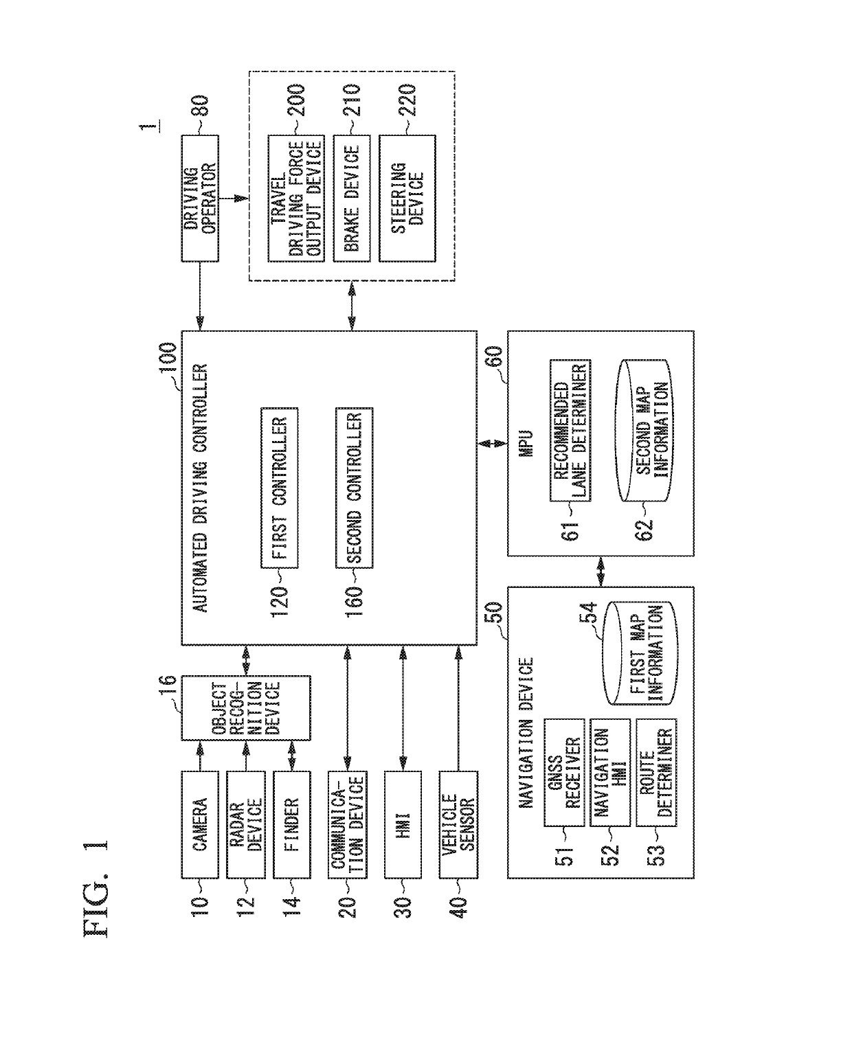
[0037]FIG. 1 is a configuration diagram of a vehicle system 1 using a vehicle control device according to a first embodiment. A vehicle in which the vehicle system 1 is mounted is, for example, a vehicle such as a two-wheeled, three-wheeled, or four-wheeled vehicle. A driving source thereof is an internal combustion engine such as a diesel engine or a gasoline engine, an electric motor, or a combination thereof. When the electric motor is used, the electric motor is operated using power generated by a generator connected to an internal combustion engine, or discharge power of a secondary battery or a fuel cell.

[0038]The vehicle system 1 includes, for example, a camera 10, a radar device 12, a finder 14, an object recognition device 16, a communication device 20, a human machine interface (HMI) 30, a vehicle sensor 40, a navigation device 50, a map positioning unit (MPU) 60, a driving operator 80, an automated driving controller 100, a travel driving forc...

second embodiment

[0101]In a second embodiment, an example in which the vehicle control device has been applied to an automated stop assistance device will be described. For example, the automated stop assistance device is not mounted on an automatedally driven vehicle as in the first embodiment, but is mounted on a vehicle in which manual driving is mainly performed.

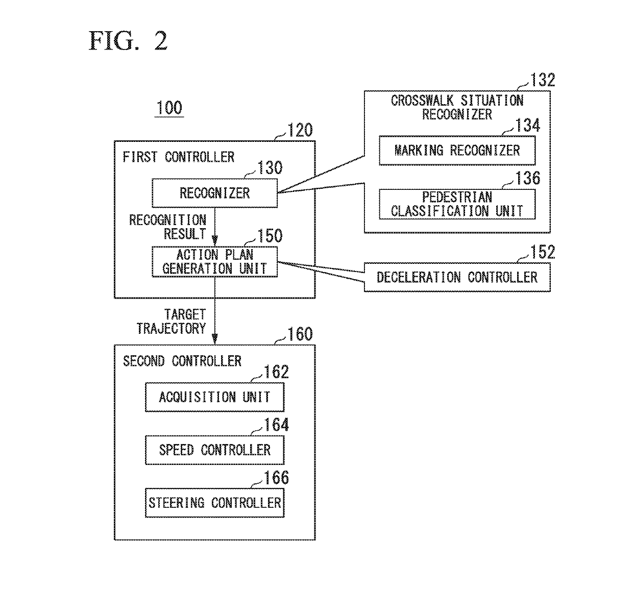
[0102]FIG. 13 is a configuration diagram of the automated stop assistance device 400 according to the second embodiment. The automated stop assistance device 400 includes, for example, a crosswalk situation recognizer 432 and a deceleration controller 452. The crosswalk situation recognizer 432 includes a marking recognizer 434 and a pedestrian classification unit 436. These components are realized, for example, by a hardware processor such as a CPU executing a program (software). Some or all of these components may be realized by hardware (including a circuitry) such as an LSI, an ASIC, an FPGA, or a GPU or may be realized by cooperatio...


PUM


Abstract

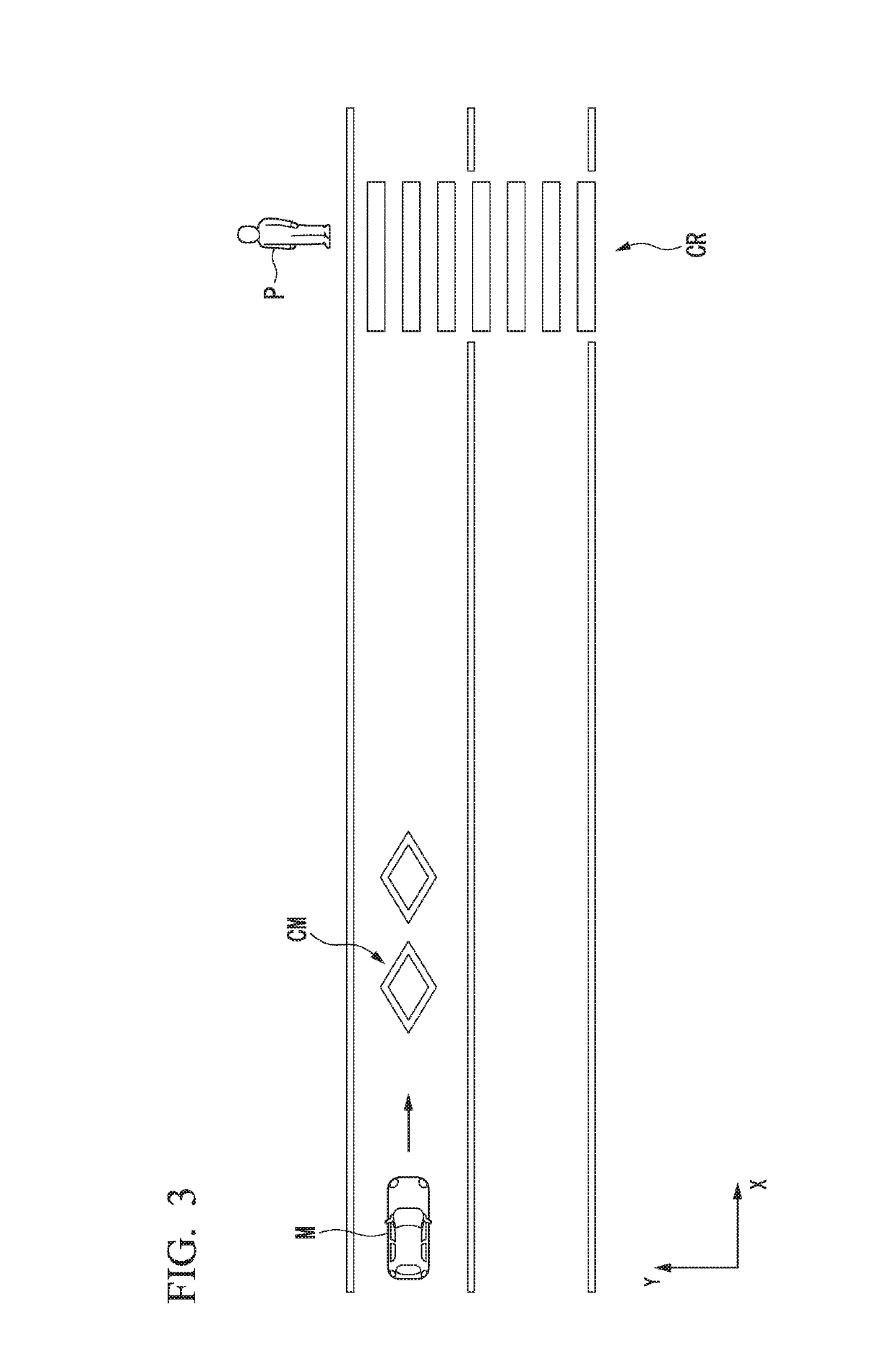
A vehicle control device (100 or 400) includes a recognizer (130 or 432) that recognizes a surrounding situation of a vehicle, and a driving controller (150 and 160, or 452) that controls at least acceleration and deceleration of the vehicle, the driving controller decelerating the vehicle with different deceleration patterns on the basis of whether a pedestrian crossing the crosswalk has been recognized by the recognizer at a point in time when a marking indicating the presence of the crosswalk in advance has been recognized by the recognizer.

Description

CROSS-REFERENCE TO RELATED APPLICATION[0001]Priority is claimed on Japanese Patent Application No. 2017-221277, filed Nov. 16, 2017, the content of which is incorporated herein by reference.BACKGROUND OF THE INVENTIONField of the Invention[0002]The present invention relates to a vehicle control device, a vehicle control method, and a storage medium.Description of Related Art[0003]In the related art, an invention of a device that brakes a subject vehicle so that both a collision between the subject vehicle and a crossing person and a collision between the subject vehicle and an oncoming vehicle are avoided when the subject vehicle crosses an opposite lane and turns right or left has been developed (see, for example, Japanese Unexamined Patent Application, First Publication No. 2017-140993).[0004]In a case in which this device detects the presence of a crossing person crossing a crosswalk near an intersection on a road that the subject vehicle tries to enter by turning right when the ...

Claims


Application Information

Patent Timeline
Patent Type & Authority Applications(United States)
IPC IPC(8): G05D1/02G06K9/00G05D1/00
CPCG05D1/0246G06K9/00798G06K9/00805G06K9/00369G05D1/0088G05D1/0223G05D2201/0213B60W2720/106B60W2720/103B60W30/0956B60W30/095B60W30/09B60W2555/60B60W2552/00B60W2554/4029B60W2554/402B60W2552/53G06V40/103G06V20/588G06V20/58
Inventor MIURA, HIROSHIISHIKAWA, MAKOTOTSUCHIYA, MASAMITSUKAWABE, KOJI
Owner HONDA MOTOR CO LTD
Learn More