Device and method for wireless communications

a wireless communication and wireless communication technology, applied in the field of wireless communication, can solve the problems of limited system performance of large-scale mimo system, inability to effectively distinguish pilot signals, and lack of orthogonal pilots, so as to reduce the pollution of pilots

Active Publication Date: 2019-05-16
SONY CORP
View PDF3 Cites 0 Cited by
  • Summary
  • Abstract
  • Description
  • Claims
  • Application Information

AI Technical Summary

Benefits of technology

[0010]With the above device and the above method, the interferences to the non-transmission objects can be significantly reduced by considering the channel information for both the transmission objects and the non-transmission objects.
[0013]With the above device and the above method, the pilot pollution can be more effectively alleviated by dividing the pilot sequences into the cell center pilot group and the cell edge pilot group.
[0016]With the above device and the above method, the communication devices in a cell are classified into the cell center communication devices and the cell edge communication devices, and pilot sequences in different pilot groups are allocated to the cell center communication devices and the cell edge communication devices. Thus, the interferences from the communication devices in the cell where the base station is located to the communication devices in a neighboring cell can be effectively avoided, thereby alleviating the pilot pollution.

Problems solved by technology

However, the system performance of the large-scale MIMO system is limited by pilot pollution problem in a scenario of, for example, multi-cell time-division multiplexing.
Specifically, since the length of the pilot is limited by a coherence length of a channel, the number of orthogonal pilots is limited, and the pilots are inevitably shared among different cells.
In this case, pilot signals transmitted by user equipments in different cells using the same pilot sequences may be received by a same base station, which, however, cannot effectively distinguish the pilot signals from each other, thereby resulting in interferences to channel estimation at the base station.
When performing uplink data detection using the interfered channel estimation, the base station may receive data from user equipments in other cells, besides data transmitted by user equipments in the cell where the base station is located, thereby resulting in inter-cell interferences in the uplink.
When the base station generates a pre-coding matrix and transmits down-link data using the interfered channel estimation, besides the user equipments in the cell where the base station is located, user equipments in other cells may also receive the data, thereby resulting in inter-cell interferences in the downlink.
Theoretical studies have demonstrated that, although both spectral efficiency and energy efficiency of the large-scale MIMO system can be significantly improved, and the influences of noises and channel estimation errors on the system performance are reduced as the number of antennas of the base station is increased, the inter-cell interferences caused by the pilot pollution cannot be eliminated and become one of the factors limiting the performance of the large-scale MIMO system.
In addition, conventional methods for alleviating the pilot pollution are often difficult to be adapted to current technical conditions.
Therefore, in actual applications, the pilot pollution is still one of the most serious problems confronted by the large-scale MIMO system.

Method used


Image

  • Device and method for wireless communications
  • Device and method for wireless communications
  • Device and method for wireless communications

Examples


first embodiment

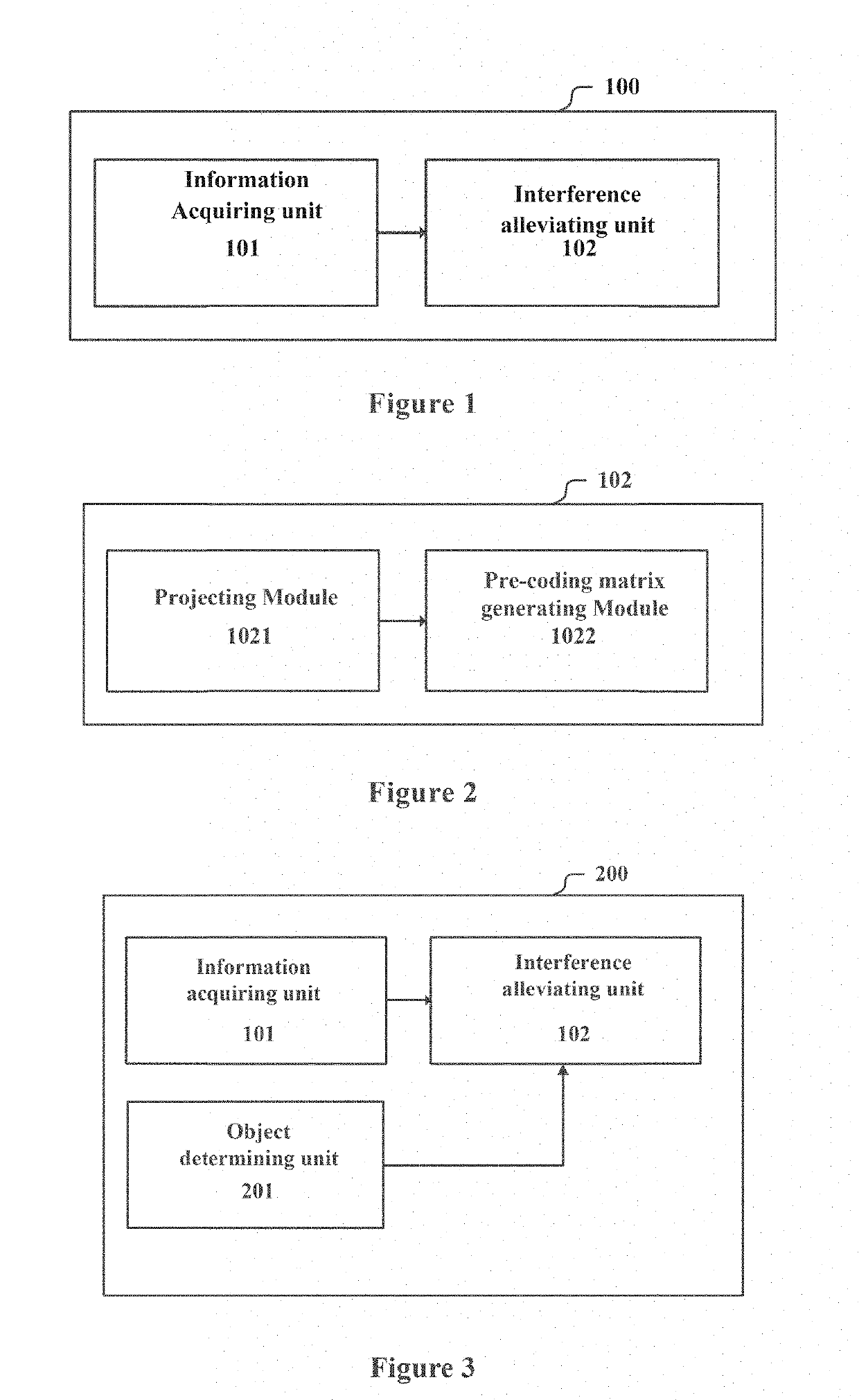
[0049]FIG. 1 illustrates a block diagram of a structure of an apparatus 100 for wireless communications according to an embodiment of the present disclosure. The apparatus 100 includes: an information acquiring unit 101, configured to acquire channel information for transmission objects and non-transmission objects of wireless communications, where transmission by the transmission objects is controlled by the apparatus 100 and transmission by the non-transmission objects is not controlled by the apparatus 100; and an interference alleviating unit 102, configured to alleviate, based on the channel information for the transmission objects and the non-transmission objects, interferences to the non-transmission objects.

[0050]For example, in cellular mobile communications, the apparatus 100 may be a base station device, the transmission objects are user equipments in a cell where the apparatus 100 is located, and the non-transmission objects are user equipments in a cell served by anothe...

second embodiment

[0080]FIG. 3 illustrates a block diagram of a structure of an apparatus 200 for wireless communications according to another embodiment of the present disclosure. Besides the components shown in FIG. 1, the apparatus 200 further includes: an object determining unit 201, configured to determine the non-transmission objects according to parameters related to interferences to the non-transmission objects, where the related parameters includes at least one of geographical locations of the non-transmission objects and signal reception situations of the non-transmission objects, and the interference alleviating unit 102 is configured to take the non-transmission objects determined by the object determining unit 201 as the non-transmission objects to which interferences are considered to be alleviated.

[0081]The apparatus 200 can appropriately select non-transmission objects to be considered during the calculation of interference alleviating by incorporating the object determining unit 201,...

third embodiment

[0095]In the following, an apparatus 300 for wireless communications according to another embodiment of the present disclosure is described with reference to FIG. 8, which illustrates a block diagram of a structure of the apparatus 300. The apparatus 300 includes: a first grouping unit 301, configured to divide pilot sequences for wireless communication into a cell center pilot group to be used for communication devices in a center of a cell and a cell edge pilot group to be used for communication devices in an edge of the cell; a second grouping unit 302, configured to divide the cell edge pilot group into multiple cell edge pilot sub-groups which do not overlap with each other; and a pilot sub-group allocating unit 303, configured to allocate different cell edge pilot sub-groups to neighboring cells, where the pilot sequences contained in the cell center pilot group are multiplexed by neighboring cells.

[0096]For example, the apparatus may be implemented as any type of server for p...


PUM


Abstract

A device and method for wireless communications. The device includes: an information acquisition unit, configured to acquire channel information about a transmission object and a non-transmission object for wireless communications, wherein the transmission of the transmission object is controlled by the device and transmission of the non-transmission object is not controlled by the device; and an interference reducing unit, configured to reduce interference with the non-transmission object based on the channel information about the transmission object and the non-transmission object.

Description

CROSS-REFERENCE TO RELATED APPLICATIONS[0001]This application is a continuation of U.S. patent application Ser. No. 15 / 513,875, filed on Mar. 23, 2017, which is based on National Stage Application PCT / CN2015 / 093075, filed on Oct. 28, 2015, which claims the benefit of priority of the Chinese Patent Application No. 201410601798.5 filed with the Chinese State Intellectual Property Office on Oct. 31, 2014, the entire disclosure of which is incorporated herein by reference.FIELD OF THE INVENTION[0002]The embodiments of the present disclosure generally relate to the technical field of wireless communications, and in particular to an apparatus and a method for wireless communications. More specifically, the embodiments of the present disclosure relate to a pilot allocation and pre-coding technology in a large-scale multi-input multi-output (MIMO) communication system.BACKGROUND OF THE INVENTION[0003]Large scale MIMO systems have been widely focused by both the academia and the industry in ...

Claims


Application Information

Patent Timeline
Patent Type & Authority Applications(United States)
IPC IPC(8): H04B7/0456H04L25/02H04L5/00H04W28/04H04W72/04
CPCH04B7/0456H04L25/0224H04L25/0204H04L5/0048H04W28/04H04W72/04Y02D70/00H04B7/0615Y02D30/70
Inventor QIAN, CHENWANG, ZHAOCHENGZHU, XUDONGCHEN, JINHUI
Owner SONY CORP
Why Eureka
Try Eureka