Deducing pressure from reopening angle

Active Publication Date: 2019-05-23
ARTEMIS INTELLIGENT POWER
View PDF7 Cites 3 Cited by
  • Summary
  • Abstract
  • Description
  • Claims
  • Application Information

AI Technical Summary

Benefits of technology

The invention provides a method for estimating the pressure of hydraulic fluid in a fluid working machine by detecting the opening or closing of valves that control the fluid's movement. This method can be used to estimate the pressure in the higher or lower pressure gallery of the machine, depending on the application. The timing of the valve opening or closing is indicative of the pressure in the other chamber, and the pressure can be estimated by detecting the event and analyzing its timing. The method can be implemented using various sensors and valve configurations, and can be used to control the machine's performance.

Problems solved by technology

However, appropriate high performance transducers can be expensive, can struggle to survive for the required service life of the hydraulic machine, can be prone to failure or present a possible failure mode or require maintenance, and can require additional wiring, increasing the complexity of machines.

Method used


Image

  • Deducing pressure from reopening angle
  • Deducing pressure from reopening angle
  • Deducing pressure from reopening angle

Examples


Embodiment Construction

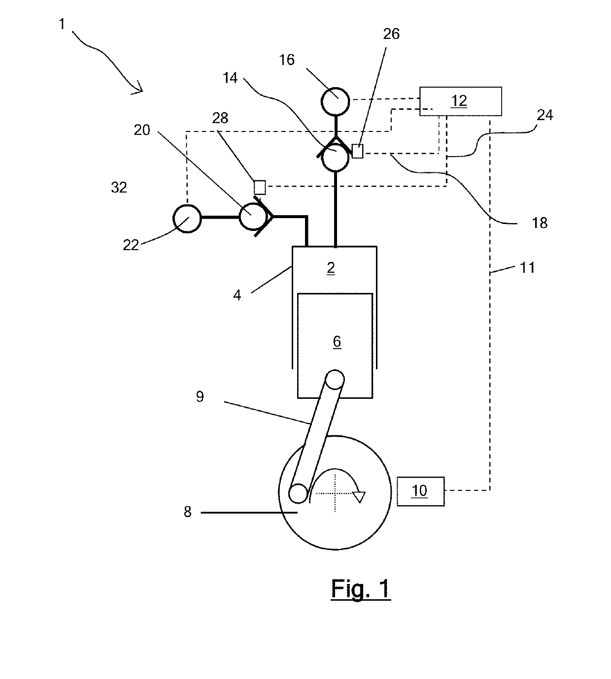
[0060]A fluid working machine 1 operable as a pump or motor includes a plurality of working chambers. FIG. 1 illustrates an individual working chamber 2 which has a volume defined by the interior surface of a cylinder 4 and a piston 6 which is driven from a crankshaft 8 by a crank mechanism 9 and which reciprocates within the cylinder to cyclically vary the volume of the working chamber. A shaft position and speed sensor 10 determines the instantaneous angular position and speed of rotation of the shaft, and informs a controller 12, by way of electrical connection 11, which enables the controller to determine the instantaneous phase of the cycles of each individual working chamber. The controller is typically a microprocessor or microcontroller which executes a stored program in use.

[0061]The working chamber comprises a low pressure valve (LPV) in the form of an electronically actuatable face-sealing poppet valve 14, which faces inwards toward the working chamber and is operable to ...


PUM


Abstract

A measurement of the pressure of hydraulic fluid in a fluid working machine can be determined from the timing of the movement of valves which selectively seal a working chamber of cyclically varying volume from a fluid gallery. The timing of opening of a low pressure valve, to connect a working chamber to a low pressure fluid gallery, following the closure of a high pressure valve to seal a working chamber can be used to estimate the pressure in the high pressure fluid gallery at the moment of closure of the high pressure valve.

Description

FIELD OF THE INVENTION[0001]The invention relates to the measurement of pressure in hydraulic fluid working machines which comprise at least one working chamber of cyclically varying volume which communicates with first and second fluid galleries through valves.BACKGROUND TO THE INVENTION[0002]Hydraulic fluid working machines include fluid-driven and / or fluid-driving machines, such as pumps, motors, and machines which can function as either a pump or as a motor in different operating modes. When a fluid working machine operates as a pump, a lower pressure fluid gallery typically acts as a net source of fluid and a higher pressure gallery typically acts as a net sink for fluid. When a fluid working machine operates as a motor, a higher pressure gallery typically acts as a net source of fluid and a lower pressure gallery typically acts as a net sink for fluid.[0003]Fluid working machines are known which comprise a plurality of working chambers of cyclically varying volume, in which th...

Claims


Application Information

Patent Timeline
IPC IPC(8): F04B49/06F03C1/013F03C1/00F04B51/00G01L7/00
CPCF04B49/065F03C1/013F03C1/002F03C1/003F04B51/00G01L7/00F04B2205/03F04B7/0076F04B53/1082F04B7/00
Inventor BRETT, MARKMCCURRY, PETER
Owner ARTEMIS INTELLIGENT POWER
Why Eureka
Try Eureka