Calibration evaluation method and device for acceleration sensor

Inactive Publication Date: 2006-01-19
NAT INST OF ADVANCED IND SCI & TECH
View PDF0 Cites 3 Cited by
  • Summary
  • Abstract
  • Description
  • Claims
  • Application Information

AI Technical Summary

Benefits of technology

[0011] Any one of the first, third, fourth and fifth mentioned acceleration sensor calibration and evaluation methods, in which the strain gauge comprises a plurality of the strain gauges attached to the side surface of the metal rod in an axial direction, further comprises converting differences in phase caused by differences in attachment position in the axial direction to a one-point measurement result, with respect to outputs of the strain gauges, based on wave propagation theory, to perform signal processing to reduce strain gauge signal noise.
[0017] Any one of the first, third, fourth and fifth mentioned acceleration sensor calibration and evaluation apparatus, wherein the strain gauge comprises a plurality of strain gauges attached in an axial direction on the side surface of the metal rod, further comprises a noise reduction means that converts differences in phase caused by differences in attachment position in the axial direction to a one-point measurement result, with respect to outputs of the strain gauges, based on wave propagation theory, to perform signal processing to reduce strain gauge signal noise.
[0019] The acceleration sensor calibration and evaluation apparatus just mentioned above further comprises signal processing means that converts differences in phase caused by differences in attachment position in the axial direction to a one-point measurement result, with respect to outputs of the plurality of strain gauges, based on wave propagation theory, to perform signal processing to reduce strain gauge signal noise.
[0026] As described in the foregoing, the present invention is configured with an acceleration sensor affixed to one end surface of the metal rod, a strain gauge attached to the side surface of the metal rod, or a laser interferometer is used to irradiate the one end surface of the metal rod with a laser beam, and a plurality of projectiles are made to impact the other end surface of the metal rod at prescribed intervals. Therefore, the effect of parasitic rolling vibration is smaller than when calibrating an acceleration sensor using a conventional vibration table, so accurate calibration is possible.
[0027] Also, since a plurality of projectiles are made to impact the other end surface of the metal rod at prescribed intervals, the duration time of the elastic wave pulses can be made longer than in the case of a single-launch impact, making it possible to calibrate at a frequency band that is best suited to the object acceleration sensor, thereby enabling more accurate results to be obtained.

Problems solved by technology

However, high acceleration cannot be generated with this evaluation apparatus, and there is also the effect of parasitic rolling vibration, making inaccurate evaluations unavoidable.
The above technique for evaluating shock acceleration simply impacts the metal rod with the metal projectile from a single launch tube, and therefore cannot generate narrower band shock acceleration having industrial significance, and in particular cannot control the launch timing, so has the drawbacks of the duration time of the generated shock acceleration being too short, and the frequency bandwidth becoming too wide.

Method used


Image

  • Calibration evaluation method and device for acceleration sensor
  • Calibration evaluation method and device for acceleration sensor
  • Calibration evaluation method and device for acceleration sensor

Examples


Embodiment Construction

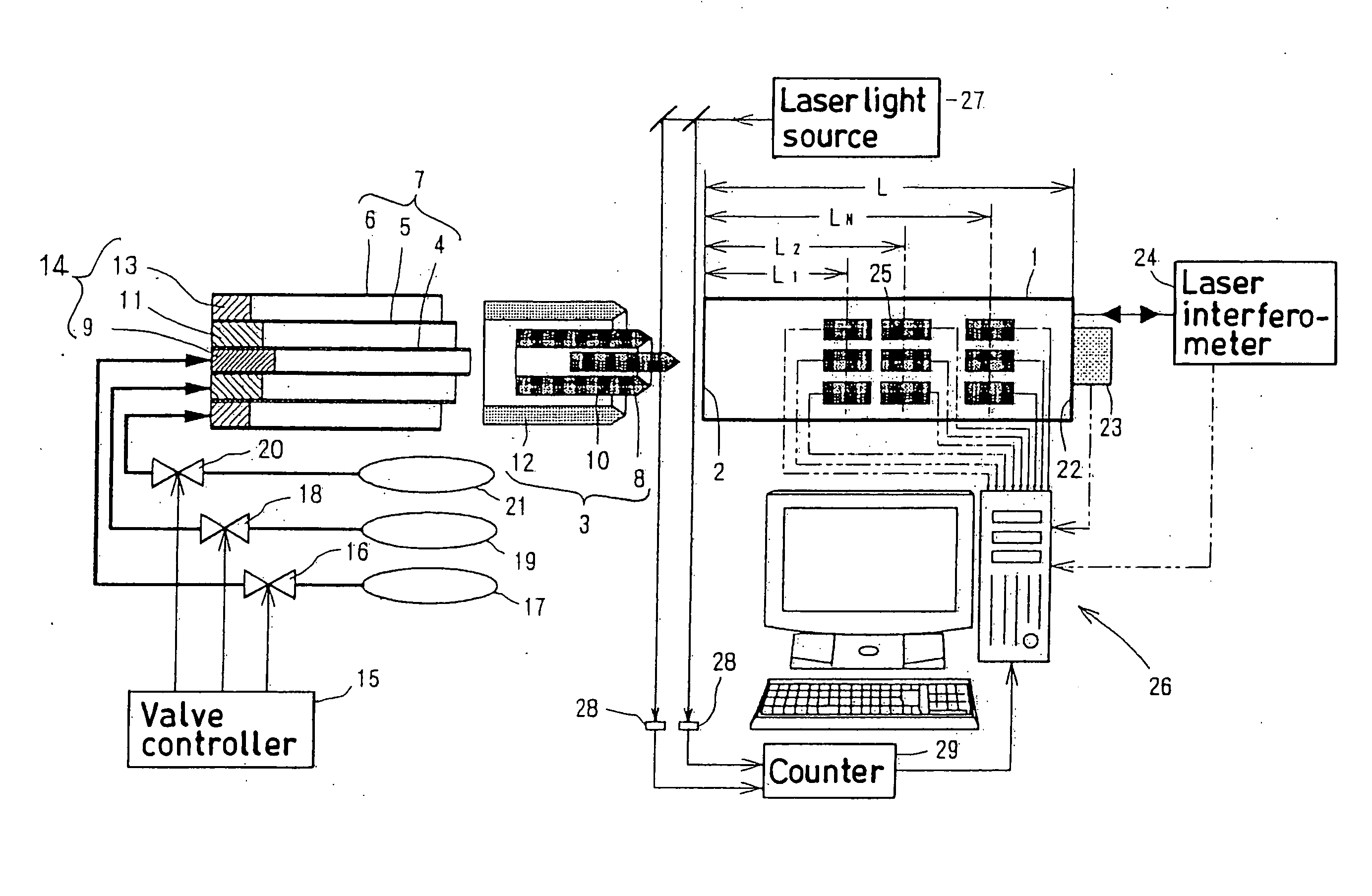
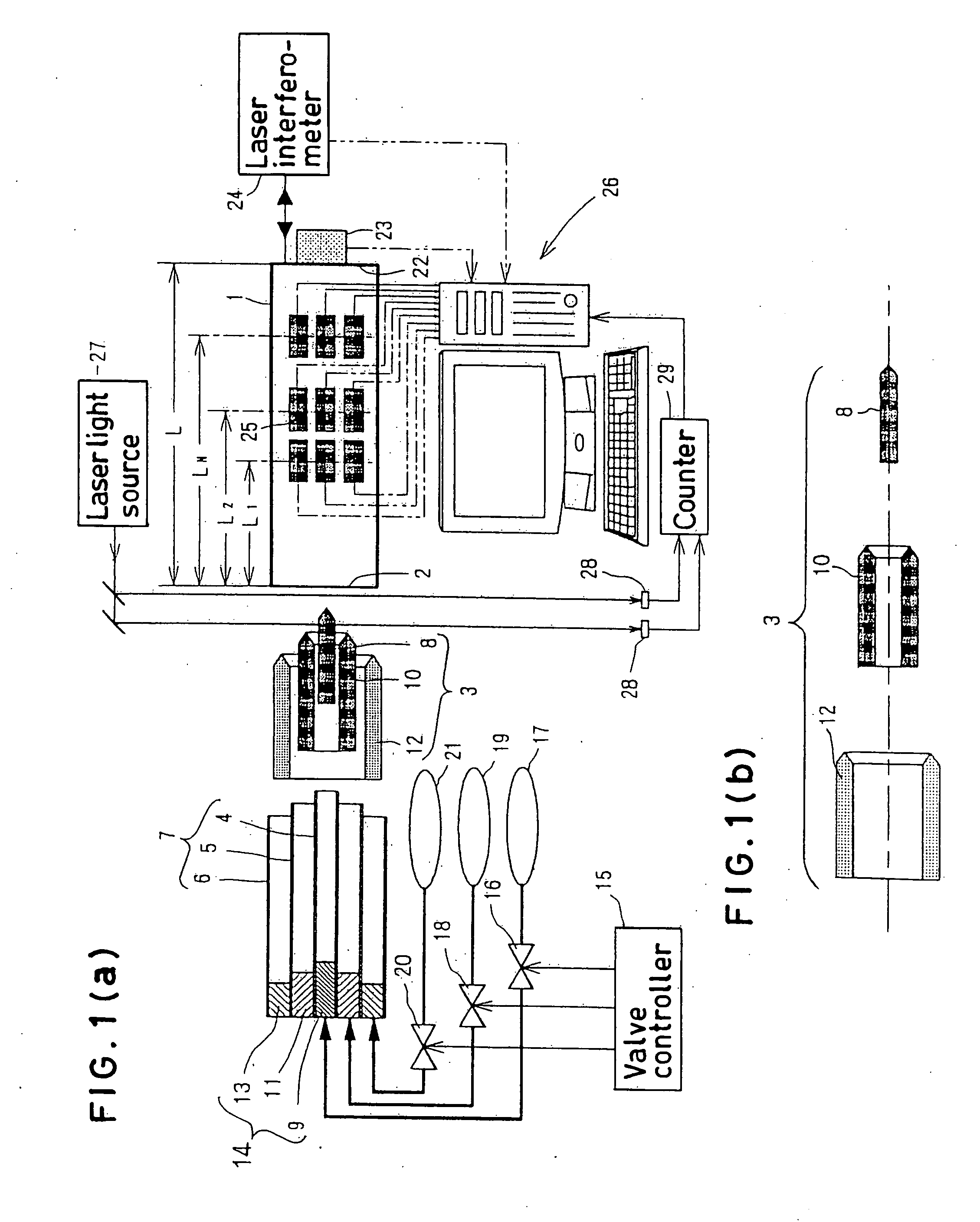
[0031]FIG. 1(a) shows an example of the acceleration sensor calibration and evaluation apparatus according to the present invention. A plurality of projectiles 3, described later, impact a first end surface 2 of a metal rod 1 to generate an elastic wave pulse therein. For doing this, a multiple launch tube 7 having n (n=1 . . . N, innermost being 1, outermost being N) tubes, is used. In the illustrated example, the multiple launch tube 7 has three launch tubes: a center launch tube 4, a middle launch tube 5 and an outer launch tube 6. A multiplicity of n (n=1 . . . N, innermost being 1, outermost being N) projectiles 3 are launched at prescribed time intervals from this multiple launch tube 7.

[0032] In the illustrated example, a cylindrical first projectile 8 can be independently launched from the interior of the center launch tube 4 by a first launch apparatus 9, an annular second projectile 10 can be independently launched from the annular space between the center launch tube 4 a...


PUM


Abstract

An acceleration sensor (22) to be calibrated and evaluated is affixed to one end surface (22) of a metal rod (1), and a plurality of projectiles (3) are made to impact the other end surface (2) of the metal rod at prescribed time intervals, generating an elastic wave pulse in the metal rod. Dynamic displacement, velocity or acceleration in a direction normal to the other end surface arising in a process of the generated elastic wave pulse reaching and being reflected by the one end surface where the acceleration sensor is affixed is measured, and an acceleration measured, processed and corrected by a strain gauge (25) attached to a side surface of the metal rod or by a laser interferometer (24) is obtained, and the corrected acceleration and the output of the acceleration sensor are compared to thereby carry out calibration and evaluation of the acceleration sensor.

Description

TECHNICAL FIELD [0001] The present invention relates to a method and apparatus for accurately and easily calibrating an acceleration sensor for detecting shock acceleration generated, for example, in car crash safety testing, robots, transportation equipment, equipment relating to nuclear power generation, ships, space and aeronautical equipment and micro-motion devices and the like. BACKGROUND ART [0002] Among acceleration sensors, shock acceleration sensors for detecting shock acceleration generated, for example, in car crash safety testing, robots, transportation equipment, equipment relating to nuclear power generation, ships, and space and aeronautical equipment and the like are widely used. When carrying out calibration and evaluation of shock acceleration sensors, conventionally, a method of installing an acceleration sensor on a mounting table of a single axis vibration table and using a laser interferometer to measure the motion of the mounting table is a technique that has...

Claims


Application Information

Patent Timeline
IPC IPC(8): G01P21/00G01P15/00
CPCG01P21/00
Inventor UMEDA, AKIRA
Owner NAT INST OF ADVANCED IND SCI & TECH
Why Eureka
Try Eureka