Position control method, position control device, and medium storage device having disturbance suppression function
- Summary
- Abstract
- Description
- Claims
- Application Information
AI Technical Summary
Benefits of technology
Problems solved by technology
Method used
Image
Examples
first embodiment
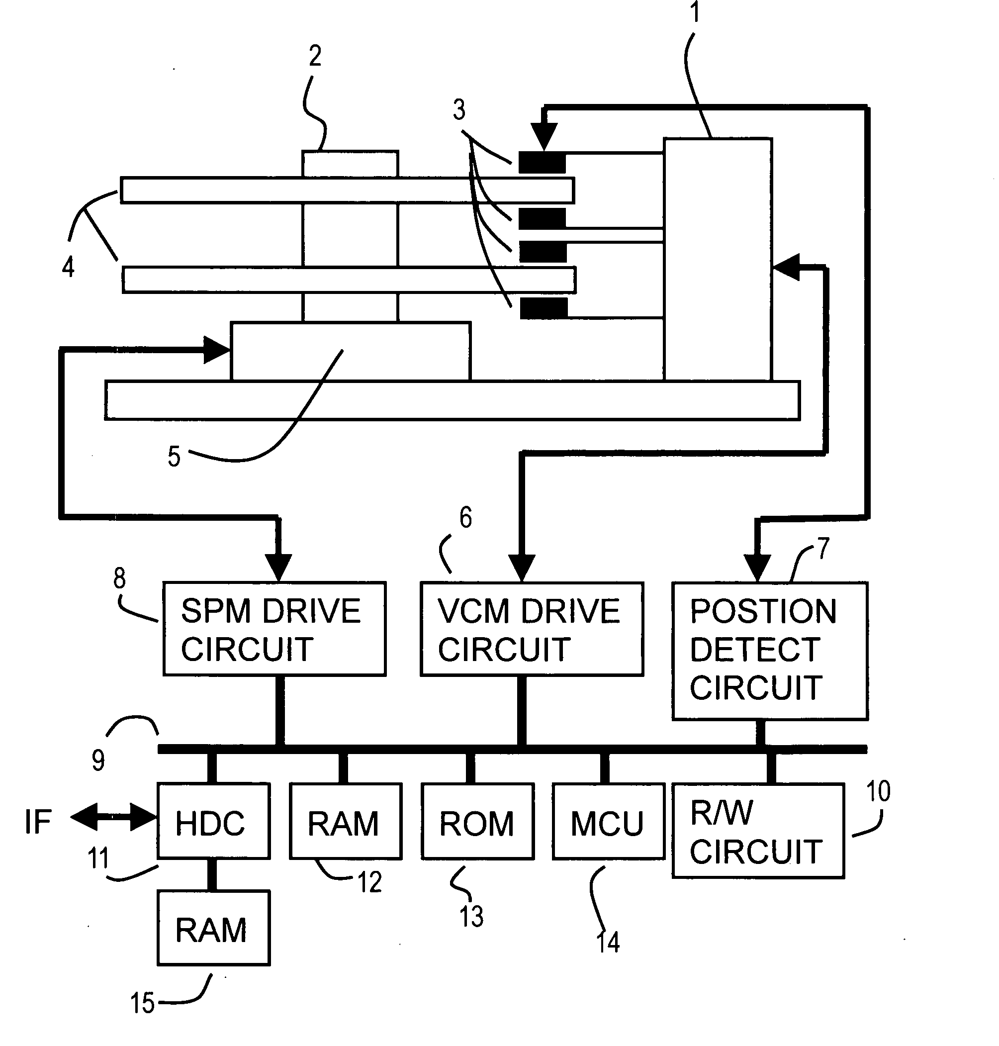
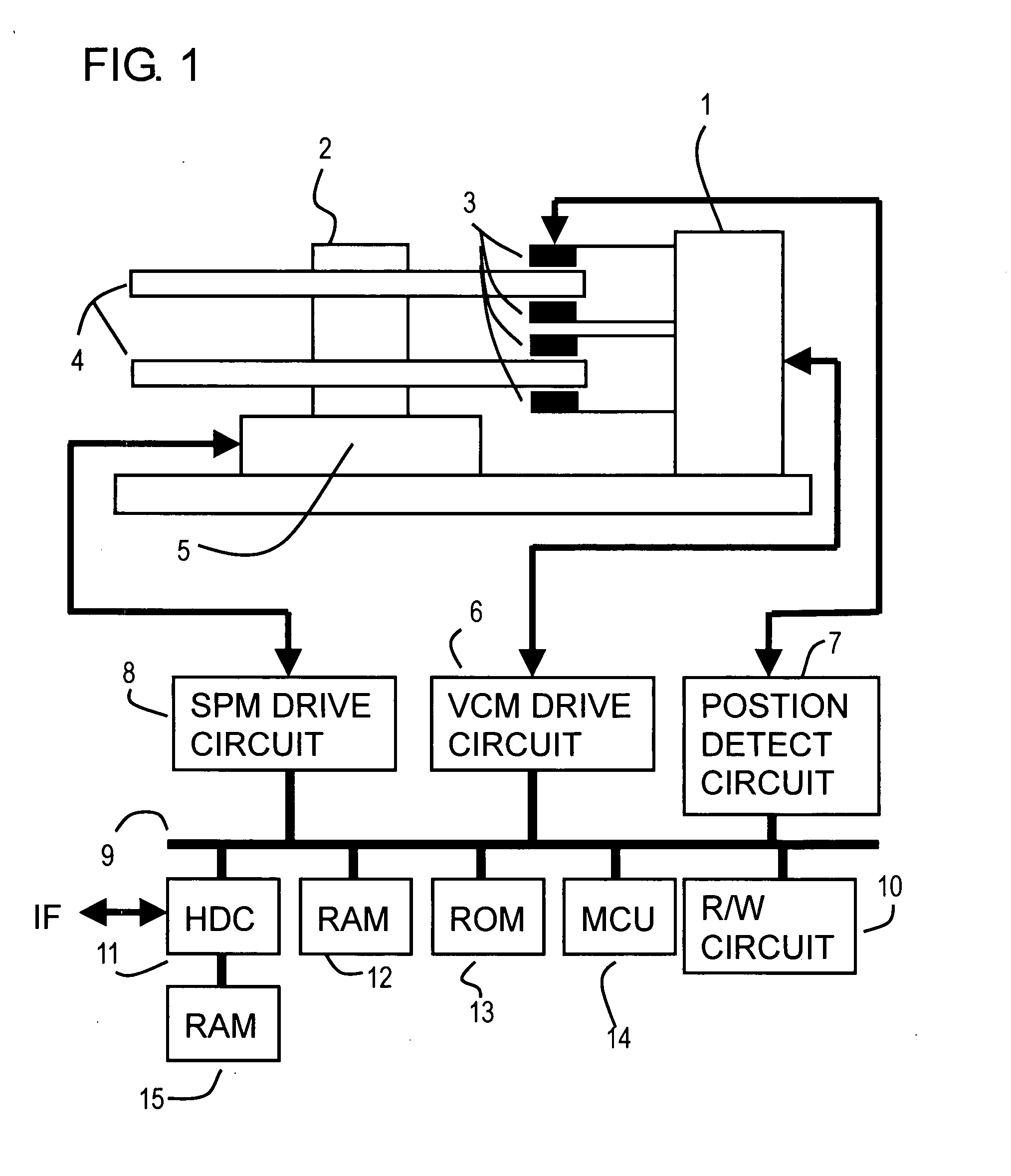
[0060]FIG. 4 is a block diagram depicting a first embodiment of the position control system of the present invention, and is a block diagram of a position control system for suppressing disturbance which the MCU 14 in FIG. 1 executes. FIG. 5 shows the target gain table in FIG. 4, and FIG. 6 and FIG. 7 are characteristic diagrams of the disturbance adaptive control in FIG. 4.
[0061]The position control system in FIG. 4 controls a disturbance suppression compensation function of a controller which is set from the outside, or according to a detected disturbance frequency Fdist. A gain adjustment function is added to this position control system. An error computing block 24 subtracts an observation position (current position) ‘y’ from a target position ‘r’ to compute a position error ‘e’.
[0062]According to the position error ‘e’, a controller 20 computes a drive instruction value ‘u’ of a plant 22 (1, 3) to make the position error ‘e’. The controller 20 computes...
second embodiment
[0080]FIG. 10 is a block diagram depicting a second embodiment of the position control system of the present invention. In FIG. 10, composing elements the same as those in FIG. 4 are denoted with the same reference symbols.
[0081]Just like FIG. 4, an error computing block 24 subtracts an observation position (current position) y from the target position r to compute a position error e. A controller 20 computes, according to position the error e, a drive instruction value u of a plant 22 (1, 3) to make the position error e zero. The controller 20 computes the drive instruction value u by a known PID control, PI control+LeadLag, and observer control, for example.
[0082]A gain multiplication block 26 multiplies the drive instruction value u from the controller 20 by a gain which is set (open loop gain), and outputs the result. A power amplifier, which is not illustrated, converts this output into a drive current I of the plant 22 (1, 3), and drives the plant 22 ...
third embodiment
[0091]FIG. 12 is a block diagram depicting a third embodiment of the position control system of the present invention, FIG. 13 is a block diagram when the control system in FIG. 12 is constructed with a current observer, and FIG. 14 is the parameter table in FIG. 13.
[0092]FIG. 12 shows a position control system for detecting a disturbance frequency and suppressing the disturbance by adaptive control, and in FIG. 12, composing elements the same as those in FIG. 4 are denoted with the same reference symbols.
[0093]In other words, an error computing block 24 subtracts an observation position (current position) ‘y’ from a target position ‘r’ to compute a position error ‘e’. According to the position error ‘e’, a controller 20 computes a drive instruction value ‘u’ of a plant 22 (1, 3) to make the position error e zero. The controller 20 computes the drive instruction value ‘u’ by an observer control to be described later in FIG. 13, for example.
[0094]A gain multiplication block 26 multip...
PUM
 Abstract
Description
Claims
Application Information
 - R&D
- Intellectual Property
- Life Sciences
- Materials
- Tech Scout
- Unparalleled Data Quality
- Higher Quality Content
- 60% Fewer Hallucinations
Browse by: Latest US Patents, China's latest patents, Technical Efficacy Thesaurus, Application Domain, Technology Topic, Popular Technical Reports.
© 2025 PatSnap. All rights reserved.Legal|Privacy policy|Modern Slavery Act Transparency Statement|Sitemap|About US| Contact US: help@patsnap.com


