X-ray tube with a catching device for backscattered electrons, and operating method therefor

Inactive Publication Date: 2010-08-12
SIEMENS AG
View PDF11 Cites 1 Cited by
  • Summary
  • Abstract
  • Description
  • Claims
  • Application Information

AI Technical Summary

Benefits of technology

[0028]During the operating state of the x-ray tube, the electrons introduce energy both in the anode as well as in the catching device, and possibly in other components. It is a further advantage of the invention that the catching device can influence the portions of the energy generated in the catching device by a suitable chosen value of the electrical potential. The portion of the total energy that is deposited in the catching device and the portion of the total energy that is deposited in the anode can be ideally configured. Ideally, all components should absorb an amount of energy that is as low as possible.
[0029]It is a further advantage that the number of electrons that are stopped in the catching device is increased by the slowing down of the electrons. It is likely that at high energy, the electrons in the scattering process emit only a part of their energy and then exit the catching device again. However this effect is small—for a potential difference of 20% to 40% between the catching device and the anode, approximately between 0.5% and 1% more energy is released in the catching device.
[0030]By applying a suitably chosen potential at the catching device, from the energy as a whole used to generate ex-rays, the portion that is converted in heat in the catching device or the anode is kept as low as possible. Therefore energy is saved in the process of generating x-rays. Also the load of the surface of the catching device is kept as low as possible. Thus the operating life of this component can be increased. Alternatively, the catching device can thus be built as a compact unit.

Problems solved by technology

However, if the energy of the electrons with renewed impact on the anode is low enough, the electromagnetic radiation generated from the electrons, at best, does not contribute the x-rays and is absorbed in the exit window.

Method used


Image

  • X-ray tube with a catching device for backscattered electrons, and operating method therefor
  • X-ray tube with a catching device for backscattered electrons, and operating method therefor
  • X-ray tube with a catching device for backscattered electrons, and operating method therefor

Examples


Embodiment Construction

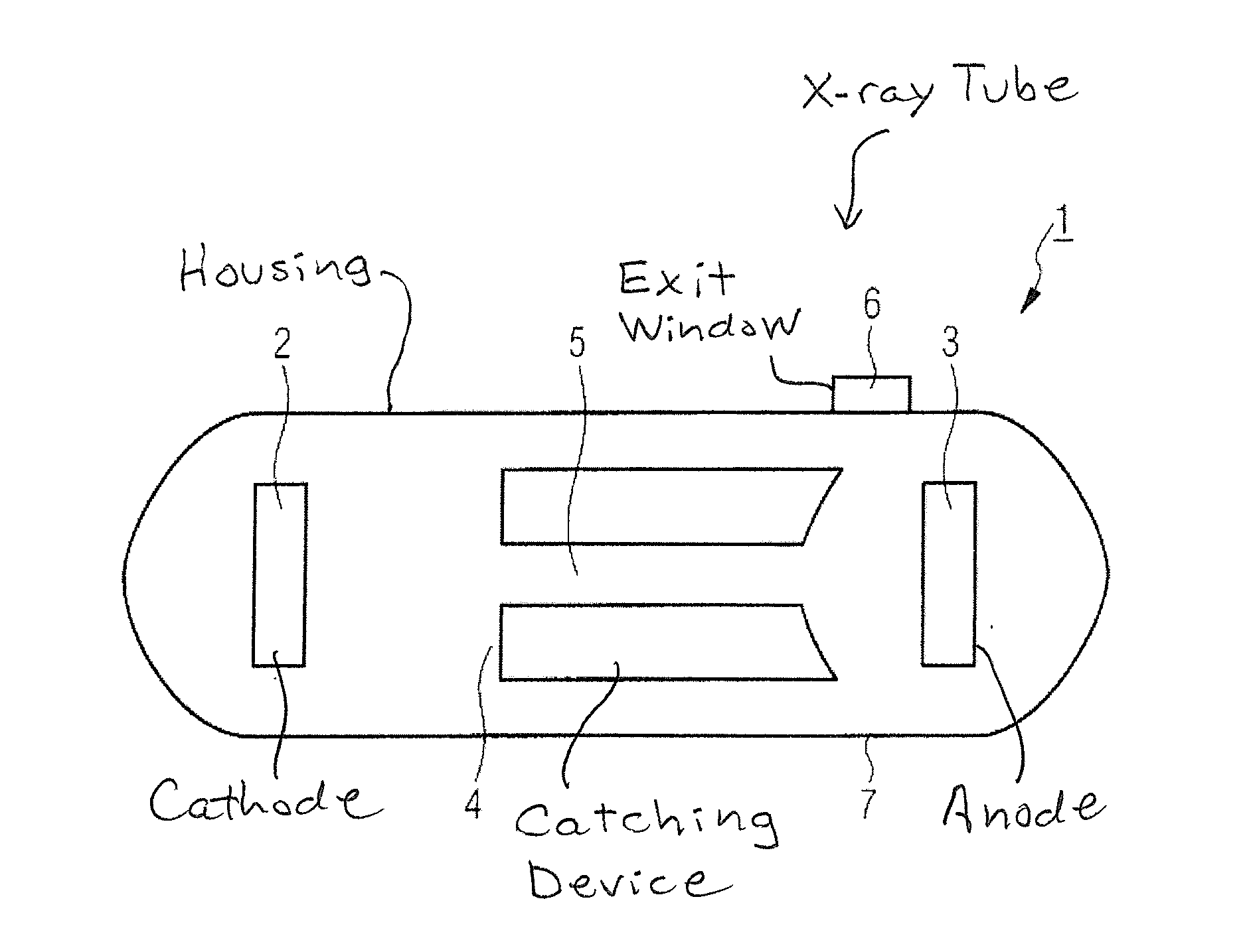
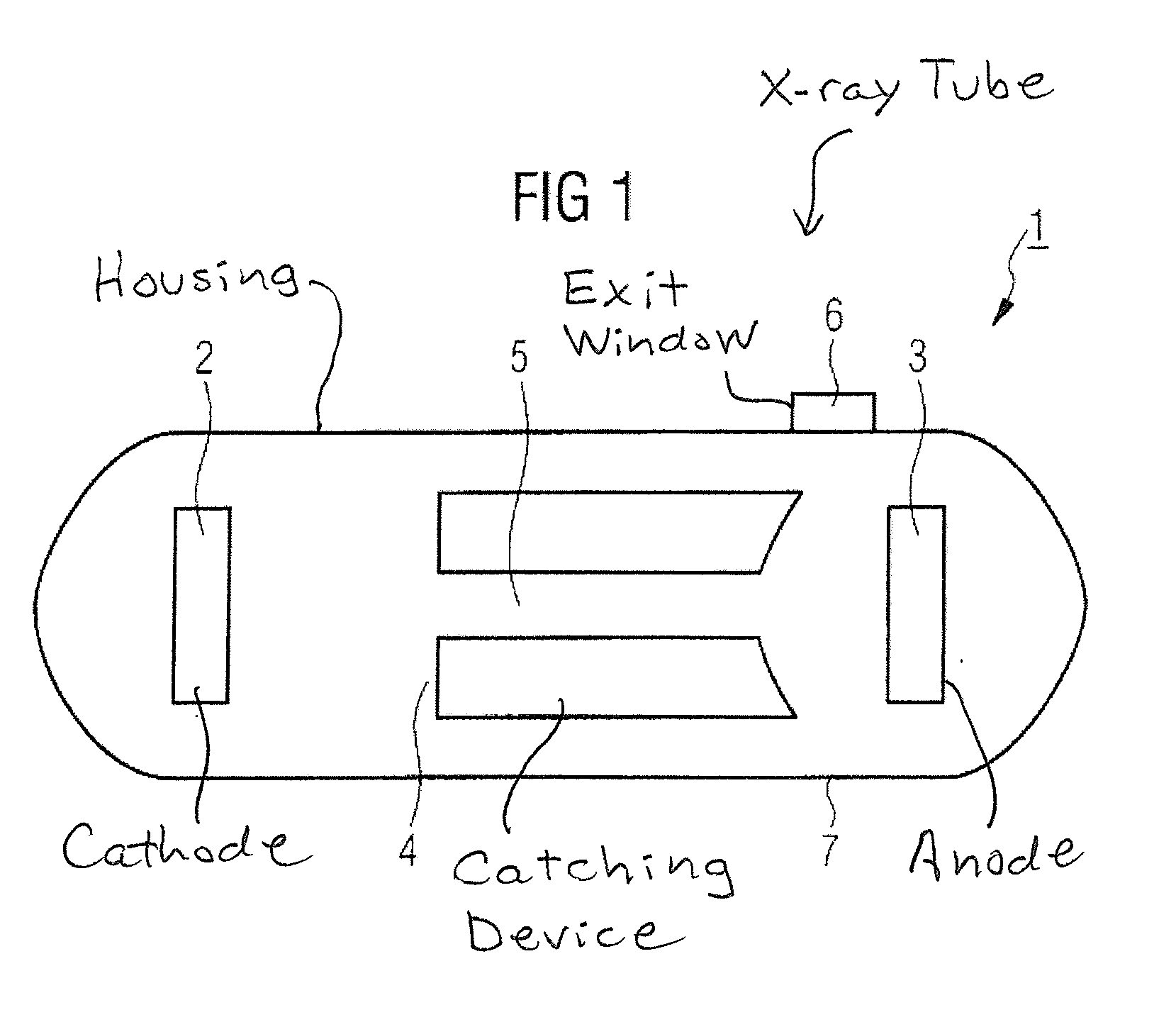
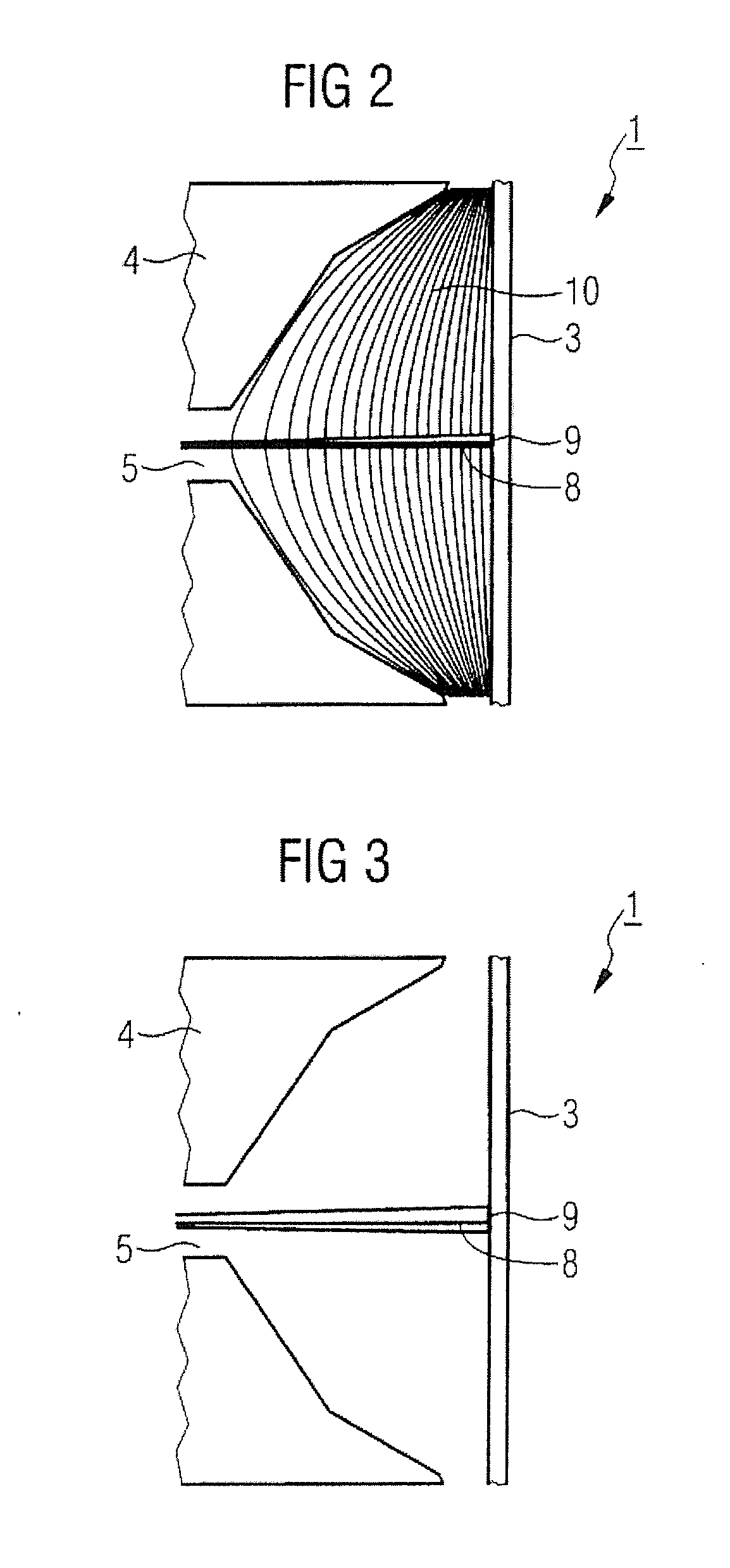
[0037]The x-ray tube 1, according to FIG. 1 has a cathode 2, an anode 3 and a catching device 4. In the operating state, the electrons that are emitted from the cathode 2 are accelerated through an electrical field in the direction of the anode 3. The electron beam path proceeds through a corridor 5 in the catching device 4 to the anode 3. When the electrons impact the anode 3 they generate x-rays, which reach the outside through an exit window 6 embedded in the housing 7 of the x-ray tube. When some of the electrons are steered back in the direction of the cathode 2, secondary processes take place. Depending on their energy, these electrons are either stopped in the catching device 4 or, if they do not reach the catching device 4, they are again accelerated in the direction of the anode 3 and there generate secondary radiation upon impact.

[0038]The catching device 4 is placed on an electric potential that causes the electrons that are backscattered from the anode 3 to be slowed dow...


PUM


Abstract

An x-ray tube has a cathode and a anode, and a catching device that captures backscattered electrons from the anode in the operating state of the x-ray tube. The catching device minimizes unwanted energy generation by the backscattered electrons in the catching device and the anode while maintaining a high quality of the focus by the catching device being electrically insulated with respect to the anode and the cathode and being placed at an electrical potential having a value between the value of the electrical potential of the anode and the value of the electrical potential of the cathode, and the amount of the difference between the potential of the catching device and the potential of the anode is in the range from 1% to 40% of the amount of the difference between the potential of the cathode and the potential of the anode.

Description

BACKGROUND OF THE INVENTION[0001]1. Field of the Invention[0002]The present invention involves an x-ray tube with a cathode and an anode and with a catching device to capture backscattered electrons from the anode in the operating state of the x-ray tube. The invention further concerns a method to operate such an x-ray tube.[0003]2. Description of the Prior Art[0004]To generate x-rays with an x-ray tube, electrons are emitted in the operating state of the x-ray tube, which are accelerated in the direction of a positively charged anode through an electric field from a negatively charged cathode. The electrons, which strike the anode in the so-called focus, release at least part of their energy there in the form of x-rays, which reach the outside of the tube through an exit window in the housing of the tube and can be used to generate radiographs.[0005]X-ray tubes can be designed with a single-pole structure, wherein the anode is grounded and the cathode is at a negative potential rel...

Claims


Application Information

Patent Timeline
IPC IPC(8): H01J35/16
CPCH01J2235/168H01J35/16
Inventor FREUDENBERGER, JOERGNEUMEIER, ERNST
Owner SIEMENS AG
Why Eureka
Try Eureka