Galvanically functionalized sensors

a functionalized sensor and galvanic technology, applied in the field of galvanically functionalized sensors, can solve the problems of limited number of reducible species in typical in-vivo measurements, high overpotential, and danger of inducing undesirable side reactions, so as to achieve the effect of reducing the number of analyte test strips, and reducing the current of the new sensor

Inactive Publication Date: 2019-05-23
ROCHE DIABETES CARE INC
View PDF3 Cites 2 Cited by
  • Summary
  • Abstract
  • Description
  • Claims
  • Application Information

AI Technical Summary

Benefits of technology

[0043]Advantageously, it was found during the work underlying the present invention, that a mediator layer like MnO2 may be electrodeposited onto a working electrode of a biosensor and that such electrodeposition leads to a homogenous, tightly adhering layer with a large surface. Also, the technical effort connected to screen printing said layer can be saved. Moreover, since the new method does not require use of a screen printing paste including DEGMBE, there are no peroxidized ethers present in the mediator layer and, thus, zero currents of the new sensors are very low. For the same reason, the new biosensors also do not require a prerun. Moreover, the using the method of the present invention, the size of a working electrode can be more exactly defined, since variability caused by screen printing is avoided. Moreover, the amount of deposited mediator can be more exactly defined during galvanic deposition. Thus, inter-lot variability of, e.g. analyte test strips, can be reduced.

Problems solved by technology

Effective oxidation or reduction of an analyte may require a high overpotential, which carries the danger of inducing undesirable side reactions.
Since most constituents of blood and interstitial fluid are present in a reduced form, the number of reducible species in typical in-vivo measurements is limited.
By encapsulation of the sensor element implanted into the body tissue, a delivery of oxygen to the working electrode may further diminish over time.
Further, the formation of gas may lead to a lift-off of a membrane which typically covers the working electrode and may even lead to a full removal of the membrane and / or the electrode.
This procedure requires labor-intensive quality control of reagents and their mixtures.
Moreover, the screen printing processes require several drying steps and, as such, are error prone by producing sensors which are incompletely printed or from which part of the layer applied has chipped off, in particular if a flexible support is used.
Moreover, the screen printing process requires the presence of solvents, of which trace amounts may remain after drying and which may interfere with measurement.
In particular, a frequently used solvent, diethylene-glycol monobutyl ether (DEGMBE), is difficult to remove entirely and may become peroxidized during manufacture, which typically causes interference in sensors detecting peroxides, e.g. glucose sensors using the glucose oxidase / H2O2 chemistry.
Further, by screen printing a reaction chemistry, enzyme (e.g. glucose oxidase) and mediator (e.g. MnO2 used for catalyzing oxidation of H2O2), though dispersed, typically are present in the reaction chemistry as aggregates, such that H2O2 must first diffuse from an enzyme aggregate to an MnO2 aggregate for detection, which decreases speed and sensitivity of detection by decreasing capture efficiency.

Method used


Image

  • Galvanically functionalized sensors
  • Galvanically functionalized sensors

Examples


example 2

Potential Stability After Partial Oxidation

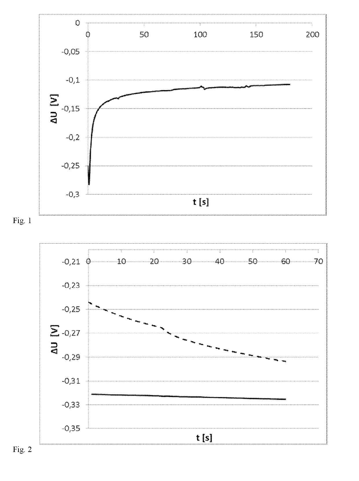
[0115]To test usability as reference electrode, the Ag-coated reference electrode of Example 1 was tested for potential stability. The electrode initially showed the expected reference potential (approx. 275-325 mV vs. manganese dioxide) without oxidation; however, the potential was not stable. After a short (10 seconds) galvanostatic oxidation at 1 μA in a chloride-ion containing solution, the potential against MnO2 was essentially constant. The ratio Ag / AgCl was adjusted via the amount of charge applied. In FIG. 2, 45 mC Ag deposition (Example 1) (dashed line) and only 10 μC oxidation to AgCl (solid line) were used, which reduced potential drift drastically.

example 3

MnO2 Deposition on a Substrate: Working Electrode

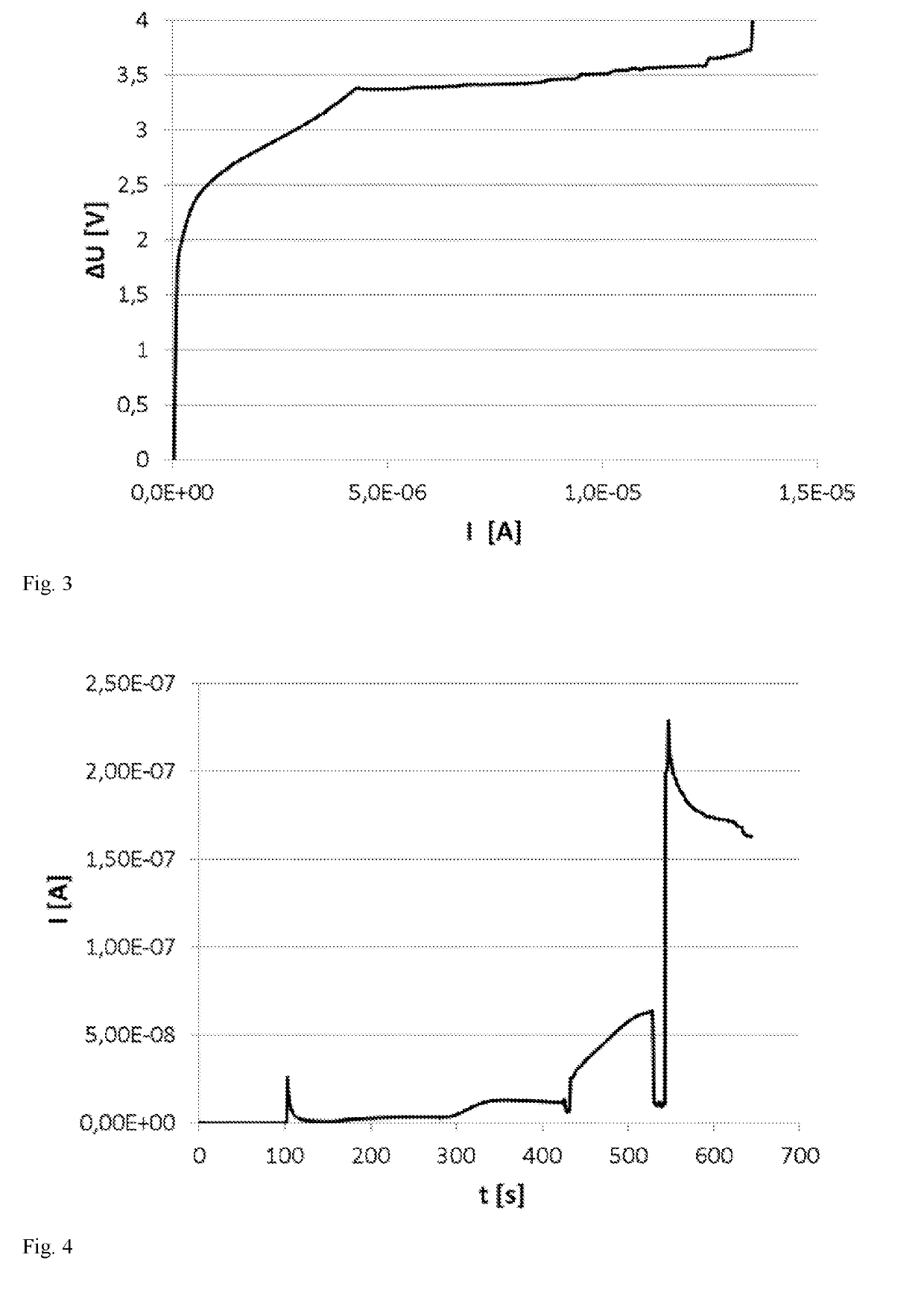
[0116]MnO2 was deposited onto multiple pads of a sensor electrode in a 2-electrode setup (working electrode, reference electrode / counter electrode, sensor reference electrode unused), using a galvanostatic CV from 0 to 15 μA (vs. reference electrode / counter electrode in Mn2+); deposition potential was 3.4 V with a disc voltage reference electrode=counter electrode at 2 V on sensor counter electrode (FIG. 3). Under these conditions, MnO2 was deposited onto all working electrode pads. Accordingly, galvanically depositing MnO2 is possible.

example 4

Functionality Testing (H2O2-Oxidation)

[0117]Functionality of the electrodeposited MnO2 in H2O2-oxidation and functionality of the Ag / AgCl reference electrode were tested in chronoamperometry at 350 mV vs. sensor reference and addition of H2O2. As shown in FIG. 4, the sensor shows an H2O2-dependent signal at 350 mV. Notably, the zero current is very low (approx. 50 pA). Moreover, a running-in of zero current is not observed, since the galvanically deposited electrode does not contain ether peroxides from the paste solvent DEGMBE.


PUM

PropertyMeasurementUnit
thicknessaaaaaaaaaa
thicknessaaaaaaaaaa
molecular weightaaaaaaaaaa

Abstract

The present invention relates to a biosensor for determining an analyte comprising a substrate, a working electrode comprising an electrically conductive pad in conductive contact with a mediator layer, and an enzyme layer in diffusion-enabling contact with said mediator layer, wherein said mediator layer is an electrodeposited mediator layer, and wherein said mediator layer comprises, in an embodiment consists of, an electrocatalytic agent. The present invention further relates to a method for manufacturing a biosensor, comprising providing a substrate having at least one conductive pad, electrodepositing a mediator layer onto at least part of said conductive pad, wherein said mediator layer comprises, in an embodiment consists of, an electrocatalytic agent, and depositing an enzyme layer onto at least part of said mediator layer. Moreover, the present invention relates to uses and methods related to the biosensor of the present invention.

Description

[0001]The present invention relates to a biosensor for determining an analyte comprising a substrate, a working electrode comprising an electrically conductive pad in conductive contact with a mediator layer, and an enzyme layer in diffusion-enabling contact with said mediator layer, wherein said mediator layer is an electrodeposited mediator layer, and wherein said mediator layer comprises, in an embodiment consists of, an electrocatalytic agent. The present invention further relates to a method for manufacturing a biosensor, comprising providing a substrate having at least one conductive pad, electrodepositing a mediator layer onto at least part of said conductive pad, wherein said mediator layer comprises, in an embodiment consists of, an electrocatalytic agent, and depositing an enzyme layer onto at least part of said mediator layer. Moreover, the present invention relates to uses and methods related to the biosensor of the present invention.[0002]The determination of the concen...

Claims


Application Information

Patent Timeline
Patent Type & Authority Applications(United States)
IPC IPC(8): G01N27/327C12Q1/00C12Q1/28A61B5/145A61B5/1468A61B5/1486
CPCG01N27/3272C12Q1/006C12Q1/004C12Q1/28A61B5/14532A61B5/1468A61B5/1486
Inventor WIEDER, HERBERT
Owner ROCHE DIABETES CARE INC
Why Eureka
Try Eureka