Torque signal dynamic compensation based on sensor location

a technology of dynamic compensation and torque signal, which is applied in the direction of engine fuction, turbine/propulsion fuel control, engine mathematical features, etc., can solve the problems of requiring maintenance and/or repairs, and affecting the accuracy of measuremen

Inactive Publication Date: 2019-05-23
PRATT & WHITNEY CANADA CORP
View PDF7 Cites 70 Cited by
  • Summary
  • Abstract
  • Description
  • Claims
  • Application Information

AI Technical Summary

Benefits of technology

[0023]In some embodiments, the program instructions are further executable by the processing unit for comparing at least one of the first torque and the second torque to associated torque limits, wherein controlling operation of the engine comprises preventing the at least one of the first torque and the second torque from surpassing the associated torque limits.

Problems solved by technology

In addition, if the torque exceeds a particular limit, one or more components of the engine may be damaged, requiring maintenance and / or repairs.
However, depending on the nature of the load connected to the output shaft, changes in behaviour of the load may interact with measurements of output torque, thereby failing to provide an accurate measurement.

Method used


Image

  • Torque signal dynamic compensation based on sensor location
  • Torque signal dynamic compensation based on sensor location
  • Torque signal dynamic compensation based on sensor location

Examples


Embodiment Construction

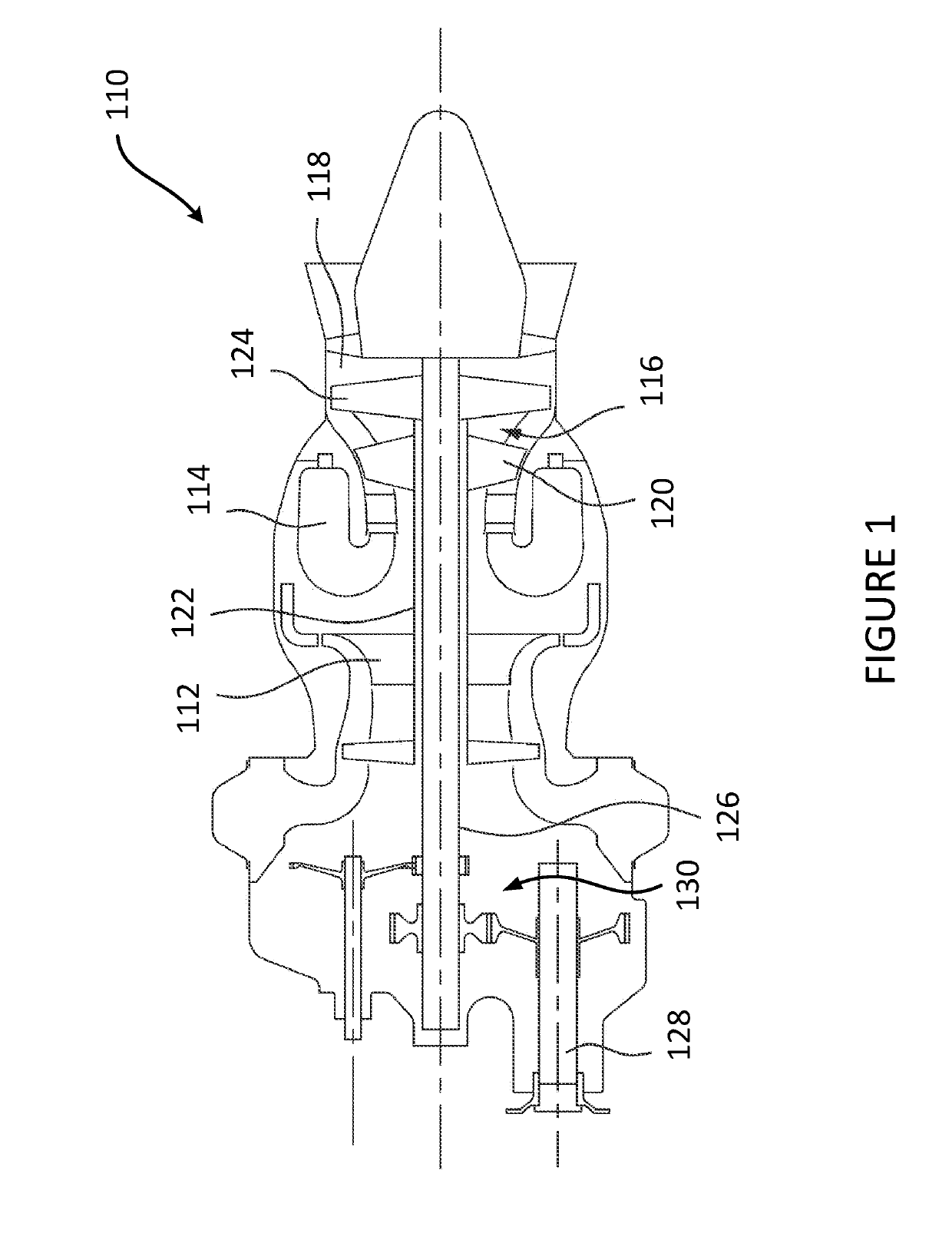
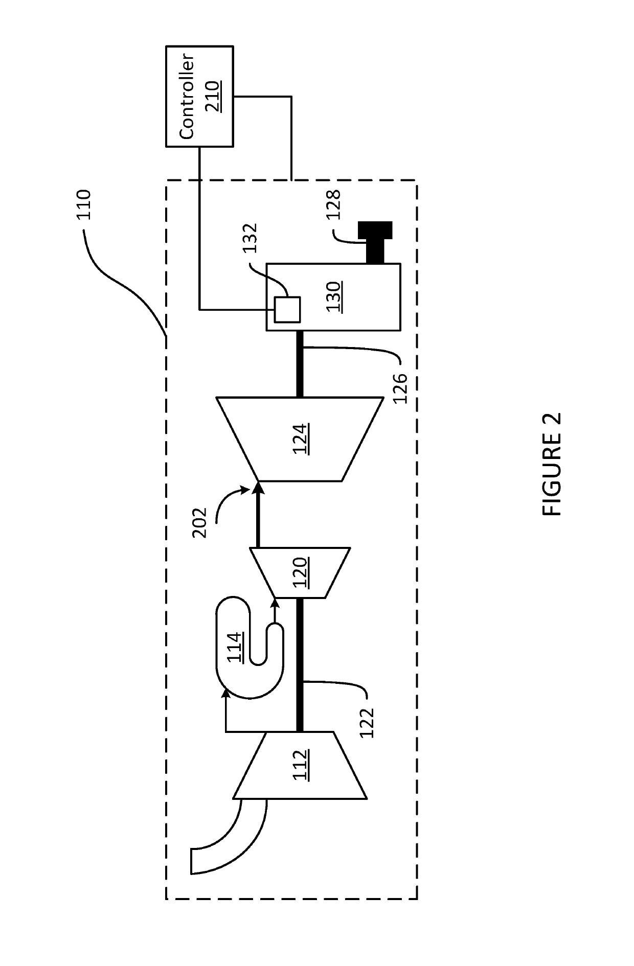
[0031]FIG. 1 illustrates a gas turbine engine 110 of a type preferably provided for use in subsonic flight, generally comprising in serial flow communication, a compressor section 112 for pressurizing the air, a combustor 114 in which the compressed air is mixed with fuel and ignited for generating an annular stream of hot combustion gases, and a turbine section 116 for extracting energy from the combustion gases. The combustion gases flowing out of the combustor 114 circulate through the turbine section 116 and are expelled through an exhaust duct 118. The turbine section 116 includes a compressor turbine 120 in driving engagement with the compressor section 112 through a high pressure shaft 122, and a power turbine 124 in driving engagement with a power shaft 126. The power shaft 126 is in driving engagement with an output shaft 128 through a gearbox 130, which may be a reduction gearbox.

[0032]Although illustrated as a turboshaft engine, the gas turbine engine 110 may alternativel...


PUM


Abstract

Herein provided are methods and systems for operating a gas-turbine engine comprising a gearbox and a power turbine coupled to the gearbox. A first torque at the gearbox is obtained via a sensor. A second torque at the power turbine is determined based on the first torque. A power at the power turbine is determined based on the second torque. Operation of the engine is controlled based on the power.

Description

TECHNICAL FIELD[0001]The present disclosure relates to control systems for gas turbine engines.BACKGROUND OF THE ART[0002]Control systems for a gas turbine engine consider a variety of parameters when regulating the operation of the engine. These parameters are collected via sensors, which may be actual physical sensors or virtual sensors, which use other measurements to derive the desired parameter. One such parameter is a value of torque output by the engine. Since output torque is representative of a value of output power, measuring output torque is useful for regulating fuel flow to the engine. In addition, if the torque exceeds a particular limit, one or more components of the engine may be damaged, requiring maintenance and / or repairs.[0003]Traditional approaches at measuring the torque at the gearbox rely on measuring torque at an output shaft of the engine, whether directly or via a virtual sensor. However, depending on the nature of the load connected to the output shaft, c...

Claims


Application Information

Patent Timeline
Patent Type & Authority Applications(United States)
IPC IPC(8): G05D17/02F02C3/113F02C7/36F02C9/28
CPCG05D17/02F02C3/113F02C7/36F02C9/28F05D2270/335F05D2270/52F05D2260/4031F05D2270/052F05D2270/06F05D2200/11F05D2200/13F05D2260/821F02C3/10F05D2260/40311
Inventor MEUNIER, GABRIEL
Owner PRATT & WHITNEY CANADA CORP
Why Eureka
Try Eureka