
Spiral forming

a spiral forming and manufacturing process technology, applied in the direction of measuring devices, profile control devices, machines/engines, etc., can solve the problems of large-scale deformation or failure of the process in the fabrication of structures, and achieve the effect of facilitating control of geometric tolerances of the resulting spiral formed structur

Active Publication Date: 2019-05-30
KEYSTONE TOWER SYST
View PDF0 Cites 2 Cited by
  • Summary
  • Abstract
  • Description
  • Claims
  • Application Information

AI Technical Summary

Benefits of technology

The patent describes a method for joining materials along a spiral joint to create conical and cylindrical structures. By controlling the alignment of the edges of the materials as they are being joined, small corrections can be made to achieve precise geometric tolerances. This results in a more accurate and reliable final spiral formed structure. Additionally, adjusting the shape of the edges can be done by introducing an out-of-plane gap, which can be easily detected and addressed. The method also uses visual indicia for easy detection of misalignment, without interfering with the structural quality of the spiral formed structure.

Problems solved by technology

While a variety of useful structures such as steel towers for wind turbines can be fabricated using this technique, the process remains susceptible to large-scale deformation or failure in fabricated structures due to small, accumulating errors in alignment and feed rates.

Method used

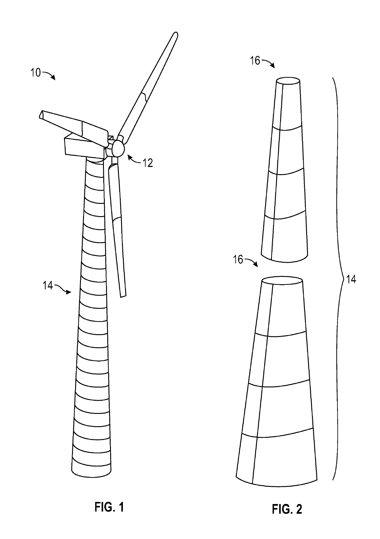
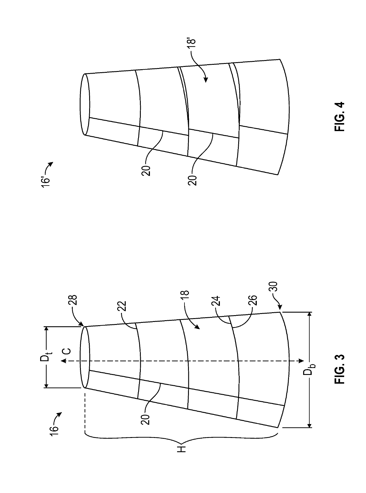
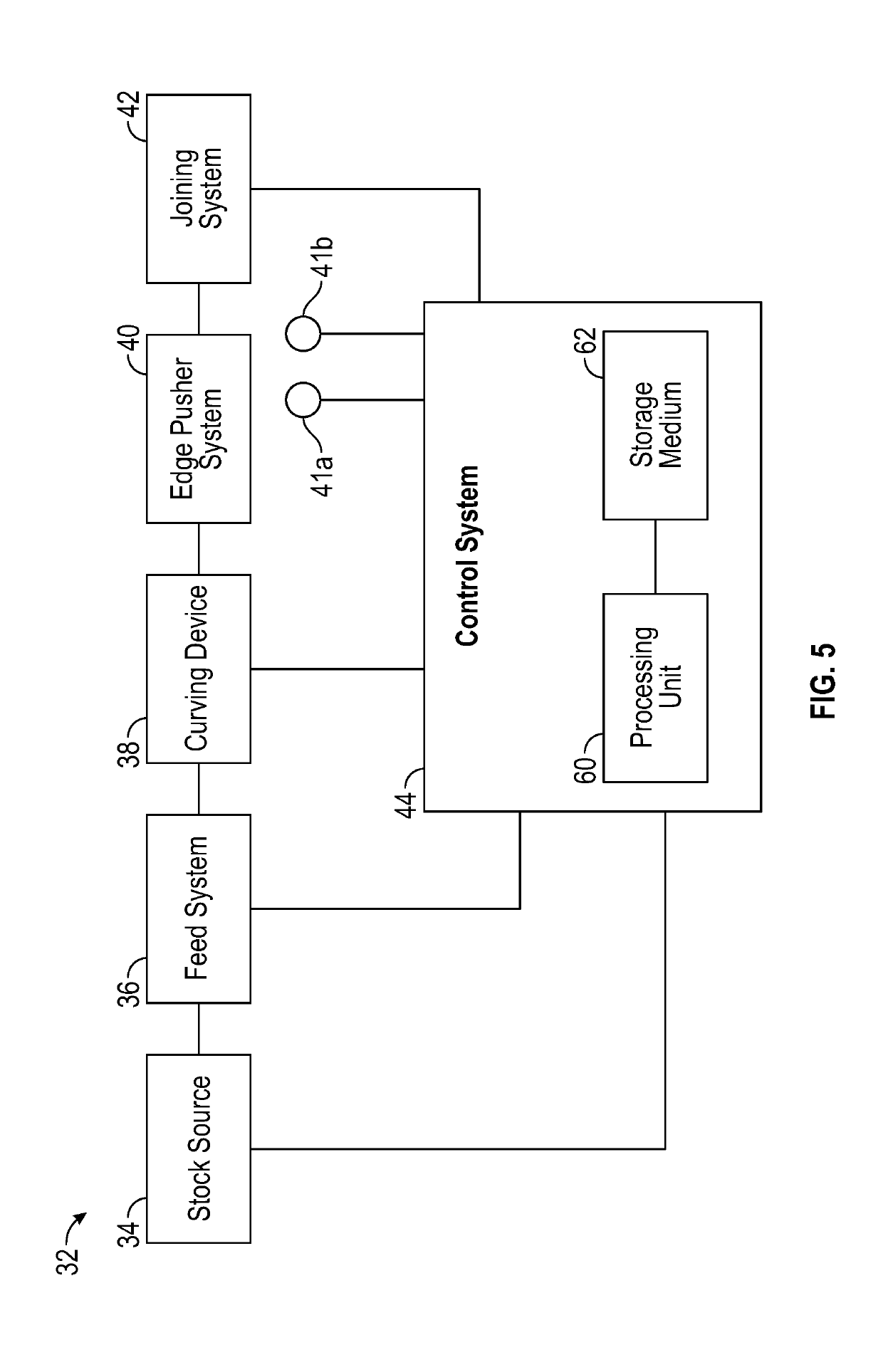

Image

  • Spiral forming
  • Spiral forming
  • Spiral forming

Examples


Embodiment Construction

[0046]The embodiments will now be described more fully hereinafter with reference to the accompanying figures, in which preferred embodiments are shown. The foregoing may, however, be embodied in many different forms and should not be construed as limited to the illustrated embodiments set forth herein.

[0047]All documents mentioned herein are hereby incorporated by reference in their entirety. References to items in the singular should be understood to include items in the plural, and vice versa, unless explicitly stated otherwise or clear from the context. Grammatical conjunctions are intended to express any and all disjunctive and conjunctive combinations of conjoined clauses, sentences, words, and the like, unless otherwise stated or clear from the context. Thus, the term “or” should generally be understood to mean “and / or” and so forth.

[0048]Recitation of ranges of values herein are not intended to be limiting, referring instead individually to any and all values falling within ...


PUM

PropertyMeasurementUnit
Forceaaaaaaaaaa
Magnetismaaaaaaaaaa
Threshold limitaaaaaaaaaa

Abstract

Spiral forming methods can be used to join edges of a rolled material along a spiral joint to form conical and / or cylindrical structures. Alignment of the edges of the rolled material can be controlled in a wrapping direction as the material is being joined along the spiral joint to form the structure. By controlling alignment of the edges of the material as the edges of the material are being joined, small corrections can be made over the course of forming the structure facilitating control over geometric tolerances of the resulting spiral formed structure.

Description

CROSS-REFERENCE TO RELATED APPLICATIONS[0001]This application is a continuation of U.S. patent application Ser. No. 15 / 191,841, filed on Jun. 24, 2016, which claims the benefit of priority of U.S. Provisional Patent Application No. 62 / 185,064, filed on Jun. 26, 2015, with the entire contents of each of the foregoing applications hereby incorporated herein by reference.GOVERNMENT LICENSE RIGHTS[0002]This invention was made with government support under NSF Phase II SBIR grant NSF IIP-1353507, awarded by the National Science Foundation. The United States government has certain rights in this invention.BACKGROUND[0003]In a spiral forming manufacturing process, a sheet of steel is fed into a mill and continuously roll-formed into a desired shape. For example, using this technique a cylinder or a conical shape can be formed by feeding sheets of suitably shaped material into the mill and continuously joining the curved, roll-formed material along a spiral edge as the material exits the mi...

Claims


Application Information

Patent Timeline
IPC IPC(8): B21C37/12B21C37/18
CPCB21C37/128B21C37/124B21C37/122B21C37/12B21C37/185F03D13/20F05B2240/912B21B38/10B21B37/00B21B37/16B21B37/38B21B38/00B21B38/04
Inventor SMITH, ERIC D.TAKATA, ROSALIND K.AINGE, DANIELBRIDGERS, LOREN DANIEL
Owner KEYSTONE TOWER SYST
Learn More