Vehicle pedal device

a pedal device and pedal pad technology, applied in the direction of mechanical control devices, gearing, instruments, etc., can solve the problems of abnormal friction, difficulty in fine adjustment of the rotation amount of the pedal pad at the initial stage of rotation etc., and achieve excellent effect, easy fine and easy adjustment of the rotation amount of the pedal pad

Active Publication Date: 2019-05-30
TOYOTA JIDOSHA KK
View PDF9 Cites 6 Cited by
  • Summary
  • Abstract
  • Description
  • Claims
  • Application Information

AI Technical Summary

Benefits of technology

[0021]When a stepping-on force is applied to the upper surface of the pedal pad and the pedal pad is displaced downward, the second link rotates in the second rotation direction against the urging force of the first urging member that is applied to the second link, and thus an urging force applied to the pressing member is increased. Therefore, a pressing force by which the pressing member presses the friction portion against the pressed portion is increased and a frictional force between the friction portion and the pressed portion is also increased.
[0022]Therefore, when there is an increase or decrease in stepping-on force that is applied to the pedal pad stopped in a state where a large stepping-on force is applied to the pedal pad, a larger static friction force is generated between the friction portion and the pressed portion at the initial stage of rotation of the pedal pad in comparison with a case where there is an increase or decrease in stepping-on force that is applied to the pedal pad stopped in a state where a relatively small stepping-on force is applied to the pedal pad. Therefore, it is possible to more easily perform a fine adjustment of the rotation amount of the pedal pad in a case where there is an increase or decrease in stepping-on force that is applied to the pedal pad stopped in a state where a large stepping-on force is applied to the pedal pad.
[0023]With the configuration as described above, the aspect of the disclosure has a more excellent effect that it is possible to easily perform a fine adjustment of the rotation amount of a pedal pad at an initial stage of rotation of the pedal pad in which a stepping-on force is applied to the pedal pad such that the pedal pad is rotated.

Problems solved by technology

Therefore, in the case of the vehicle pedal device in JP 2010-73143 A, it is difficult to perform a fine adjustment of the rotation amount of the pedal pad at the initial stage of rotation of the pedal pad.
When the foreign substance enters the area between the friction portion and the pressed portion, there may be abnormal friction.

Method used


Image

  • Vehicle pedal device
  • Vehicle pedal device
  • Vehicle pedal device

Examples


modification examples

Other Modification Examples

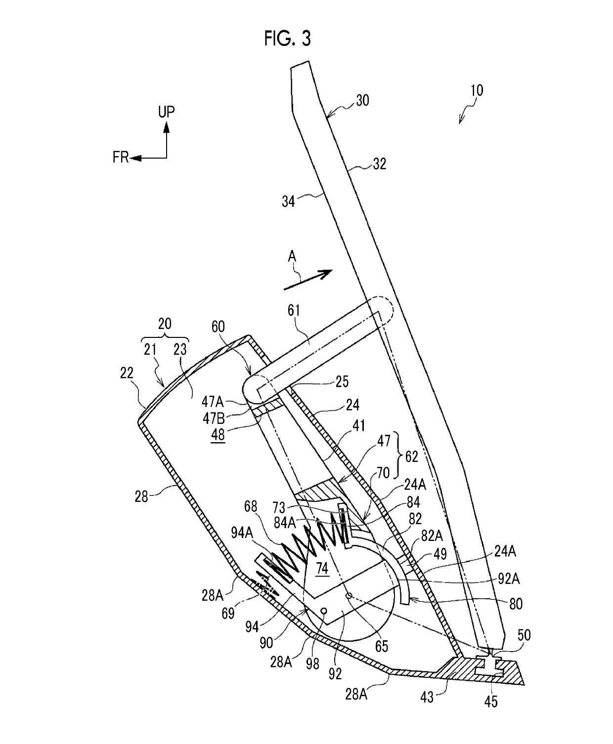
[0118]In the embodiment, the pressed portion 49 is provided on the inner wall of the upper wall 24 of the housing 20. However, the configuration is not limited to this. The pressed portion 49 may be the inner wall itself of the upper wall 24 of the housing 20. That is, the pressed portion may be a contact surface such as a wall surface or the like formed on a constituent portion of a wall portion or the like constituting a portion of the housing 20.

[0119]In the embodiment, the second link 62 is provided with the slider 80 that is rubbed with the pressed portion 49. However, the configuration is not limited to this. for example, the friction portion that is rubbed with the pressed portion 49 may be a friction surface formed on a constituent portion of the second link 62. The friction portion may be integrally provided with the second link 62.

[0120]In the embodiment, the coil spring 68 urges the second link 62 via the slider 80. However, the configuration is...


PUM


Abstract

A vehicle pedal device includes: a pedal pad; a housing provided below the pedal pad and provided with a through-hole; a first link passing through the through-hole, a first end portion of the first link being rotatably connected to the pedal pad, a second end portion of the first link being disposed in the housing; a second link, a first end portion of the second link being rotatably connected to the second end portion of the first link, a second end portion of the second link being supported in the housing, a first urging member configured to urge the second link in a rotation direction in which the pedal pad is displaced upward; and a friction portion pressed against a pressed portion provided in the housing and configured to apply a rotation resistance to the second link.

Description

CROSS-REFERENCE TO RELATED APPLICATIONS[0001]This application claims priority to Japanese Patent Application No. 2017-229535 filed on Nov. 29, 2017, which is incorporated herein by reference in its entirety including the specification, drawings and abstract.BACKGROUND1. Technical Field[0002]The disclosure relates to a vehicle pedal device.2. Description of Related Art[0003]Japanese Unexamined Patent Application Publication No. 2010-73143 (JP 2010-73143 A) discloses a vehicle pedal device as described below. That is, in the vehicle pedal device in JP 2010-73143 A, a first end portion of a first link is rotatably connected to a pedal pad of which a lower end portion is rotatably supported. A second end portion of the first link is rotatably connected to a first end portion of a second link. A second end portion of the second link is supported in a housing such that the second end portion can rotate in a first rotation direction in which the pedal pad is displaced upward and a second r...

Claims


Application Information

Patent Timeline
Patent Type & Authority Applications(United States)
IPC IPC(8): G05G5/05B60K26/02F16H21/44G05G1/44
CPCG05G5/05B60K26/02F16H21/44G05G1/44G05G2505/00G05G5/03G05G25/04B60K26/021
Inventor KADOI, HIRONORI
Owner TOYOTA JIDOSHA KK
Why Eureka
Try Eureka