
Variable torque electric motor assembly

a technology of electric motors and torque, applied in the field of magnetic flux regulation of electric machines, can solve problems such as power limitation of pmdcm

Active Publication Date: 2019-05-30
HAMILTON SUNDSTRAND CORP
View PDF1 Cites 2 Cited by
  • Summary
  • Abstract
  • Description
  • Claims
  • Application Information

AI Technical Summary

Benefits of technology

This solution allows for efficient power delivery under a wide range of conditions, reduces the need for larger or stronger magnets, and enhances fault tolerance by enabling the motor to adapt torque and power output dynamically, thus improving power density without increasing size or cost.

Problems solved by technology

A PMDCM is limited in power by the available flux developed by the magnets on the rotor of the motor.

Method used


Image

  • Variable torque electric motor assembly
  • Variable torque electric motor assembly
  • Variable torque electric motor assembly

Examples


Embodiment Construction

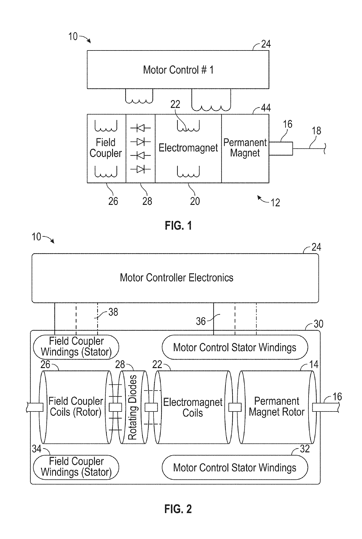
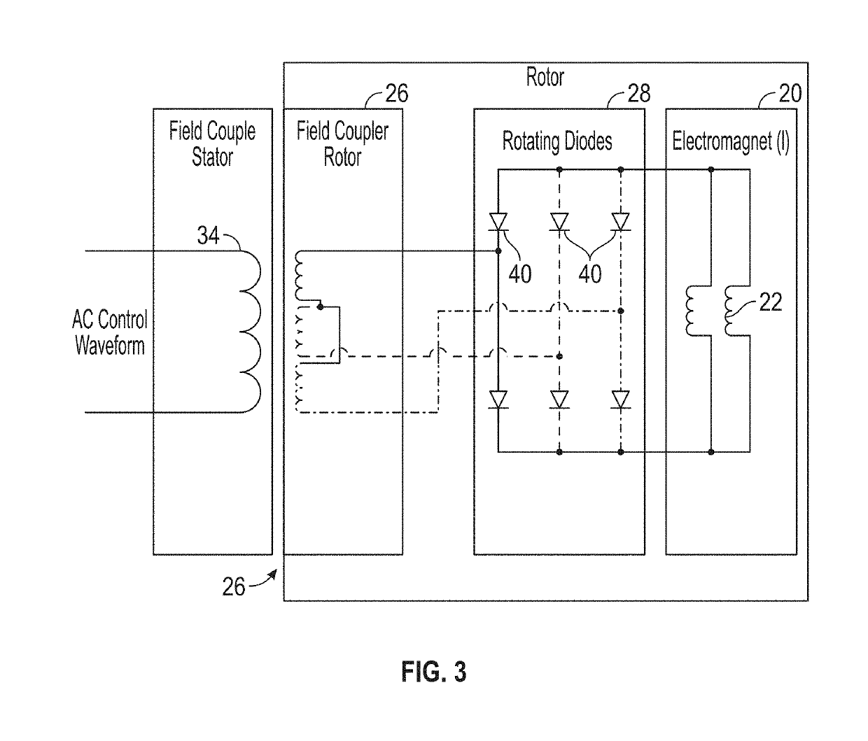
[0033]Devices, systems and methods are provided herein for control of an electric motor. An embodiment of a motor assembly includes an electric motor (e.g., a permanent magnet DC motor) having a stator assembly and a rotor assembly. A controllable magnetic device is coupled to the rotor assembly and can be actuated and / or controlled to control an amount of magnetic flux in the rotor assembly. In one embodiment, the controllable magnetic device is an electromagnet formed by one or more windings that are mounted on a rotor shaft or otherwise coupled to the rotor assembly so that the windings rotate concurrently with the rotor assembly. The controllable magnetic device may be configured to increase the magnetic flux to, for example, increase the torque of the motor assembly and / or increase the power of an actuator coupled to the motor assembly. The controllable magnetic device can also be configured to decrease the magnetic flux.

[0034]In one embodiment, the controllable magnet device i...


PUM


Abstract

An actuator assembly includes an electric motor including a rotor assembly and a stator assembly configured to be actuated to cause the rotor assembly to rotate based on an amount of magnetic flux in the rotor assembly is disclosed. The assembly also includes a controllable magnetic device coupled to the rotor assembly, an actuator coupled to the rotor assembly; and a controller configured to apply electric current to the controllable magnetic device to adjust an amount of torque provided by the electric motor by adjusting the magnetic flux in the rotor assembly.

Description

BACKGROUND OF THE INVENTION[0001]The subject matter disclosed herein relates to electric machines. More specifically, the subject disclosure relates to magnetic flux regulation of electric machines.[0002]Many electrical actuators employ a DC electric motor, such as a Permanent Magnet DC Motor (PMDCM) to move a surface or object. Typically, the size of the actuator is related to the available power that must be delivered. In some cases, electrical actuators are needed to be able to deliver maximum power under a wide range of conditions and faults.[0003]A PMDCM is limited in power by the available flux developed by the magnets on the rotor of the motor. In conventional PMDCMs, the magnetic field strength dictates the size of the rotor, because the rotor holds the permanent magnet(s). The higher the power, the more magnetic flux is needed, either through larger size or stronger magnets.BRIEF DESCRIPTION OF THE INVENTION[0004]According to one aspect of the invention an actuator assembly...

Claims


Application Information

Patent Timeline
Patent Type & Authority Applications(United States)
IPC IPC(8): H02P6/32H02P25/03H02P6/08
CPCH02P6/32H02P25/03H02P6/08H02K19/12H02K21/042H02K2213/06
Inventor POISSON, RICHARD A.MASTROCOLA, NAISON E.
Owner HAMILTON SUNDSTRAND CORP
Features
  • Generate Ideas
  • Intellectual Property
  • Life Sciences
  • Materials
  • Tech Scout
  • Unparalleled Data Quality
  • Higher Quality Content
  • 60% Fewer Hallucinations
Learn More