
Devices and methods to prevent joint instability following arthroplasty

a technology of joint instability and arthroplasty, which is applied in the direction of prosthesis, catheter, application, etc., can solve the problems of affecting knee function, affecting knee function, and affecting knee function,

Active Publication Date: 2019-06-06
EXACTECH INC
View PDF0 Cites 20 Cited by
  • Summary
  • Abstract
  • Description
  • Claims
  • Application Information

AI Technical Summary

Benefits of technology

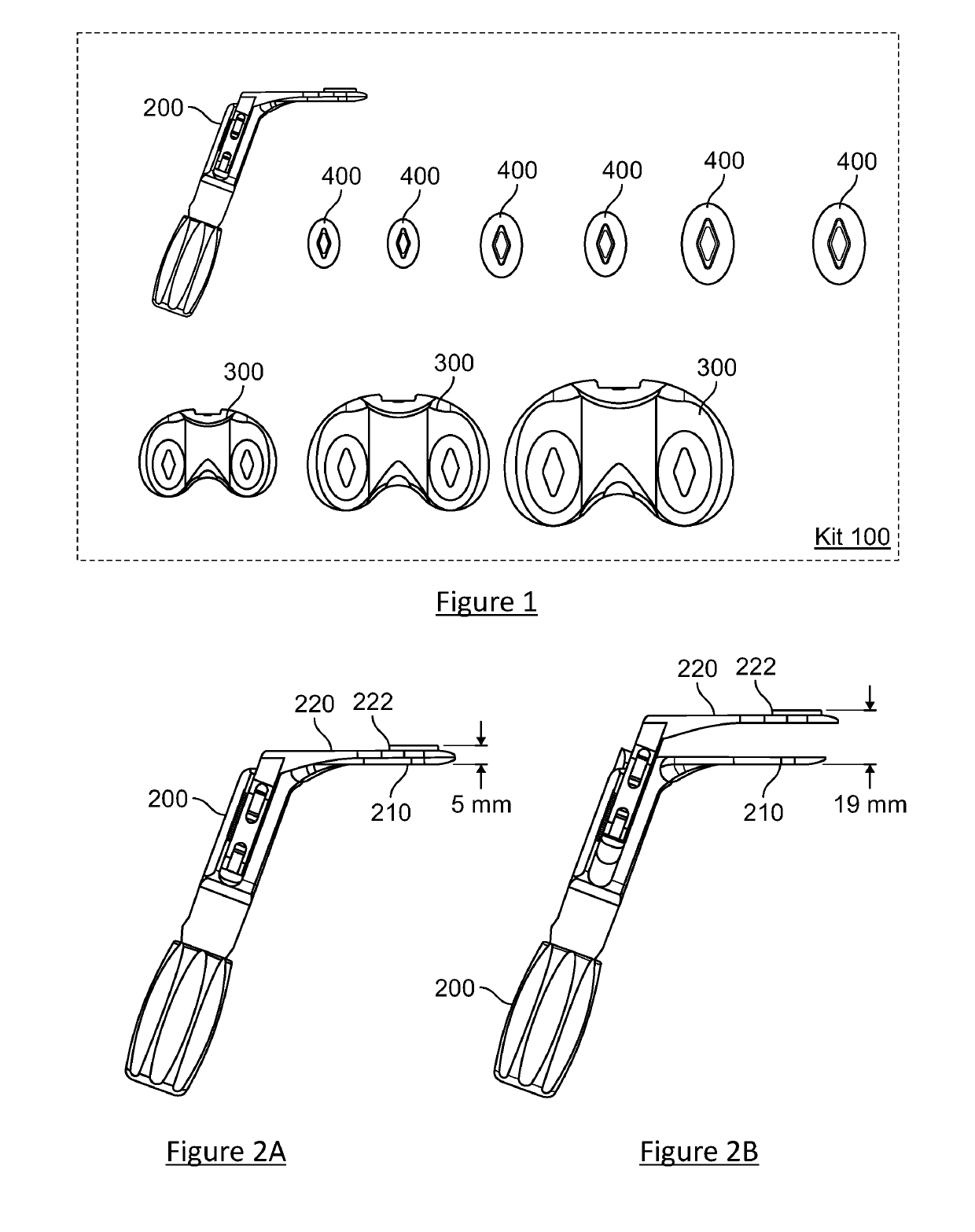
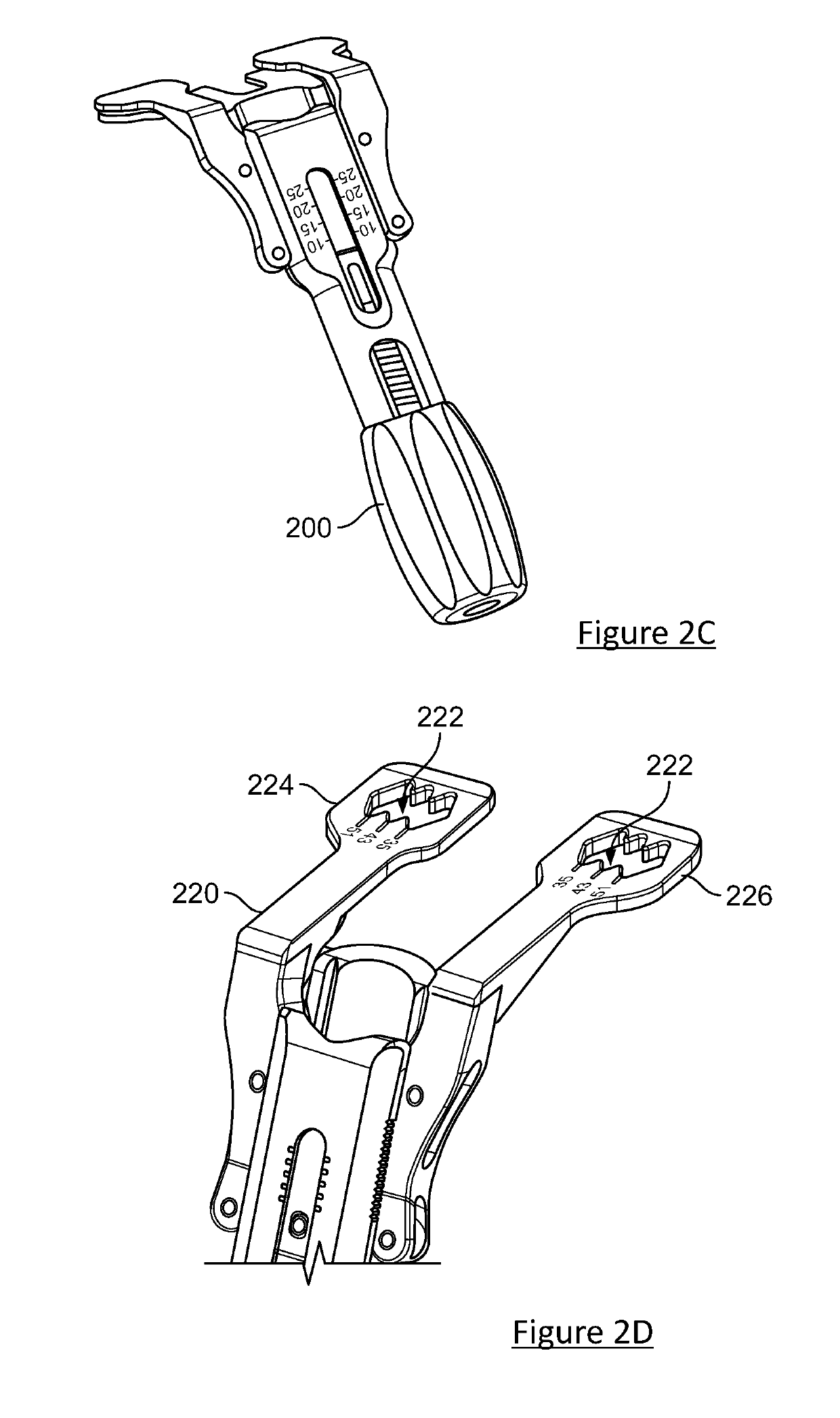
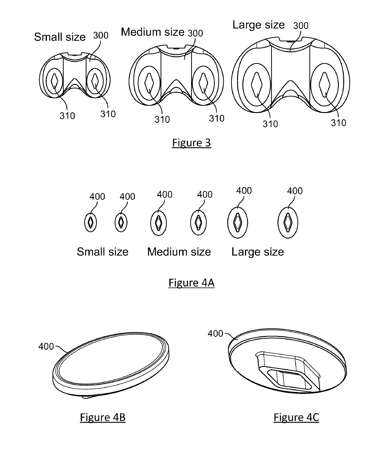
The present invention provides a kit for preparing bones for joint replacement surgery. The kit includes an alignment guide for preparing the bones, a distractor for separating the bones, and a plurality of trial elements for evaluating the suitability of different surgical implants. The trial elements are designed to be temporarily coupled to the bones and receive sensors for recording various parameters such as force, orientation of force, pressure mapping, joint gap, and contact location. The kit also includes a computing device for displaying and analyzing the recorded data. The technical effects of the invention include improved accuracy in bone preparation and joint replacement surgery, reduced soft tissue damage, and improved outcomes.

Problems solved by technology

Using the knee as a non-limiting example, joint instability occurs when the soft-tissue structures around the knee are unable to provide the stability necessary for adequate function during standing or walking.
Following arthroplasty, instability may be the result of increased soft-tissue laxity (looseness) due to improper positioning and / or alignment of the prosthesis.
Pain and / or a sensation of the knee “giving way” may alter knee function and require revision surgery.
Joint instability is one of the major causes of revision after total knee arthroplasty (TKA).
Currently, techniques to increase joint stability are imprecise.
The amount of soft-tissue to be released to obtain a balanced knee is often uncertain.
Similarly, the amount of bone to be re-cut in order to correct the balance of the knee is difficult to assess.

Method used


Image

  • Devices and methods to prevent joint instability following arthroplasty
  • Devices and methods to prevent joint instability following arthroplasty
  • Devices and methods to prevent joint instability following arthroplasty

Examples


Embodiment Construction

[0053]Among those benefits and improvements that have been disclosed, other objects and advantages of this invention will become apparent from the following description taken in conjunction with the accompanying figures. Detailed embodiments of the present invention are disclosed herein; however, it is to be understood that the disclosed embodiments are merely illustrative of the invention that may be embodied in various forms. In addition, each of the examples given in connection with the various embodiments of the invention which are intended to be illustrative, and not restrictive.

[0054]The present invention will be further explained with reference to the attached drawings, wherein like structures are referred to by like numerals throughout the several views. The drawings shown are not necessarily to scale, with emphasis instead generally being placed upon illustrating the principles of the present invention. Further, some features may be exaggerated to show details of particular...


PUM


Abstract

A kit includes a distractor, a plurality of trial elements, and at least one sensor. The distractor is configured to separate a first bone from a second bone by adjusting the distance between a first member and a second member, and is configured to receive at least one sensor in the first portion. Each of the trial elements corresponds to one of a plurality of surgical implants, is configured to be temporarily coupled to the second bone so as to evaluate suitability of the corresponding one of the plurality of surgical implants for implantation, and is configured to receive at least one sensor. The at least one sensor is configured to be received in the distractor or one of the trial elements, and is configured to record a magnitude of a force, a direction of application of a force, a pressure mapping, or a location of application of a force.

Description

CROSS-REFERENCE TO RELATED APPLICATION[0001]This is an international (PCT) application relating to and claiming the benefit of commonly-owned, copending U.S. Provisional Patent Application No. 62 / 372,487, filed Aug. 9, 2016, entitled “DEVICES AND METHODS TO TREAT JOINT INSTABILITY FOLLOWING ARTHROPLASTY,” the contents of which are incorporated by reference herein in their entirety.TECHNICAL FIELD[0002]Various embodiments of the present invention relate to methods and systems to optimize the position and orientation of components in order to decrease the occurrence of joint instability after total joint arthroplasty. In particular, various embodiments of the present invention relate to methods and systems to optimize the position and orientation of components in order to decrease the occurrence of joint instability after total knee arthroplasty.BACKGROUND[0003]Using the knee as a non-limiting example, joint instability occurs when the soft-tissue structures around the knee are unable...

Claims


Application Information

Patent Timeline
Patent Type & Authority Applications(United States)
IPC IPC(8): A61F2/46A61B17/02A61F2/38
CPCA61F2/4657A61B17/025A61F2/4684A61F2/3859A61F2/389A61F2/461A61B2017/0268A61F2002/4666A61F2002/30616A61F2002/4658A61F2002/4632A61F2002/4668A61F2002/30125A61F2002/30148A61F2002/30153A61F2002/30154A61B5/1036A61B5/1076A61B5/4585A61B2090/064A61B2017/00075A61B2034/105A61B2034/2051
Inventor ANGIBAUD, LAURENT
Owner EXACTECH INC
Learn More