Head voltage correcting method for inkjet printing apparatus, an apparatus using same, and a program thereof

a technology of inkjet printing and head voltage, which is applied in the direction of instruments, visual presentations, computing, etc., can solve the problems of inability to make similar adjustments for adjacent head modules to uniform density, inability to accurately correct the head voltage, and inability to disperse ink droplets in error, etc., to achieve efficient and accurate processing

Active Publication Date: 2019-06-06
DAINIPPON SCREEN MTG CO LTD
View PDF2 Cites 0 Cited by
  • Summary
  • Abstract
  • Description
  • Claims
  • Application Information

AI Technical Summary

Benefits of technology

[0008]This invention has been made having regard to the state of the art noted above, and its object is to provide a head voltage correcting method for inkjet printing apparatus, and an apparatus using the same, capable of easily uniforming ink droplet density for a plurality of head modules while inhibiting the deterioration of print quality, which is achieved by devising testing charts.

Problems solved by technology

However, despite whatever adjustment is made in advance, when the head modules are installed on the apparatus, a defective dispensation of ink droplets may occur due to electrical characteristics of the board which drives the head modules or slight displacements of the head modules.
Print quality will deteriorate particularly when excessive distances occur between the main droplets and satellite droplets.
However, the conventional example with such construction has the following problem.
This poses a problem that, even if the adjustment is made for one head module, it may be impossible to make similar adjustment also for adjacent head modules to uniform density, or may require very complicated adjustment.

Method used


Image

  • Head voltage correcting method for inkjet printing apparatus, an apparatus using same, and a program thereof
  • Head voltage correcting method for inkjet printing apparatus, an apparatus using same, and a program thereof
  • Head voltage correcting method for inkjet printing apparatus, an apparatus using same, and a program thereof

Examples


Embodiment Construction

[0039]One embodiment of this invention will be described hereinafter with reference to the drawings.

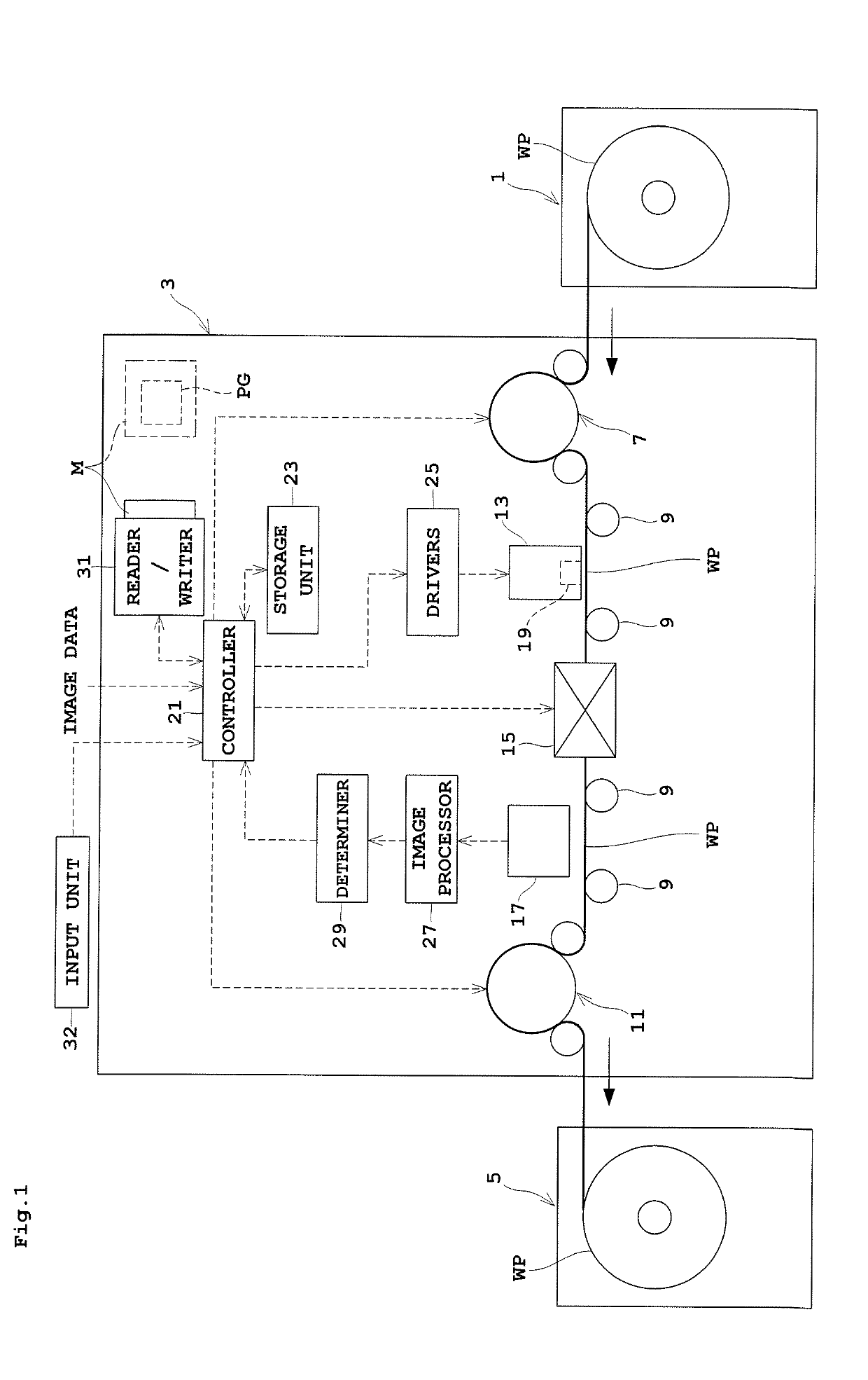
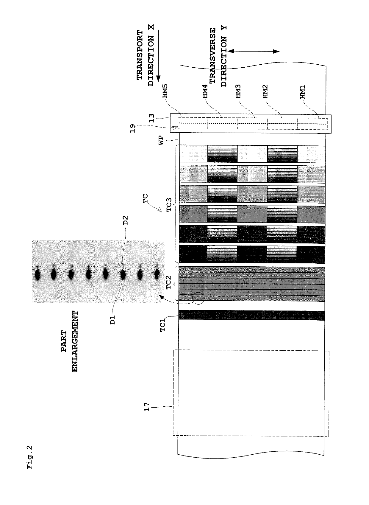
[0040]FIG. 1 is an outline schematic view showing an entire inkjet printing system according to the embodiment. FIG. 2 is a plan view of a head and web paper with testing charts printed thereon.

[0041]The inkjet printing system according to this embodiment includes a paper feeder 1, an inkjet printing apparatus 3 and a takeup roller 5.

[0042]The paper feeder 1 holds web paper WP in a roll form to be rotatable about a horizontal axis, and unwinds and feeds the web paper WP to the inkjet printing apparatus 3. The inkjet printing apparatus 3 performs printing on the web paper WP. The takeup roller 5 takes up on a horizontal axis the web paper WP printed in the inkjet printing apparatus 3. Referring to the side of feeding the web paper WP as upstream and that of discharging the web paper WP as downstream, the paper feeder 1 is located upstream of the inkjet printing apparatus 3, and the tak...


PUM


Abstract

A head voltage correcting method for inkjet printing apparatus which perform printing with a head having a plurality of head modules includes the following steps: a testing chart printing step for printing testing charts which includes a lowest density head module check pattern, satellite check patterns, band-by-band density variable patterns, and in-band density variable patterns; a lowest density head module determining step for determining a lowest density head module; a satellite-free drive voltage determining step; and a new reference voltage determining step for determining a drive voltage of the band-by-band density variable patterns of the adjacent head module to be a new reference voltage for the adjacent head module.

Description

BACKGROUND OF THE INVENTION(1) Field of the Invention[0001]This invention relates to a head voltage correcting method for inkjet printing apparatus which perform printing on a printing medium by dispensing ink droplets thereto, to an apparatus using the same, and to a program thereof. In particular, the invention relates to a technique of voltage correction in a head having a plurality of head modules arranged in a direction perpendicular to a printing medium transport direction, each head module having a plurality of nozzles.(2) Description of the Related Art[0002]An inkjet printing apparatus performs printing by dispensing ink droplets from head modules to a printing medium. Since there are an individual difference from one head module to another and a question of print quality, adjustment is made at the time of manufacture to be capable of dispensing ink droplets in a predetermined density level which satisfies the specifications, and a voltage used at that time is set as referen...

Claims


Application Information

Patent Timeline
Patent Type & Authority Applications(United States)
IPC IPC(8): B41J2/21B41J29/393
CPCB41J2/2139B41J29/393B41J2/2142B41J2029/3935B41J2/2146G06K15/027B41J2/04558B41J2/04516
Inventor MURAMATSU, ASUKANOMURA, SEIYA
Owner DAINIPPON SCREEN MTG CO LTD
Why Eureka
Try Eureka